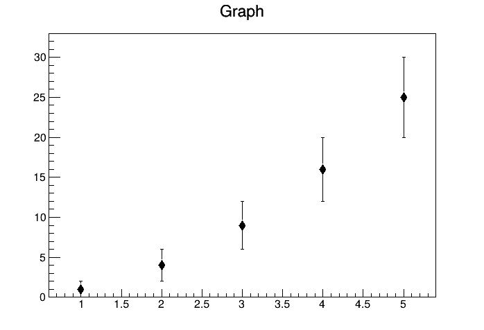
I’m having an issue when trying to use marker style 33 (full diamond) with TGraphErrors. It seems like the markers are offset by 1 pixel to the right and 1 pixel down, leading to a pixel of whitespace above the marker and one pixel on the right of the marker being cut off.
For reference, the resulting markers look like this:
I don’t see that problem when I run your macro. Try first with a more recent version of ROOT; if that doesn’t solve it:
Maybe it’s an artifact on your display: maybe you have scaling on your screen (if you see the problem on an interactive session, but if you save the canvas you shouldn’t see it on the saved image); or try a different canvas size
I tried upgrading to the newest stable version of ROOT at time of writing, version 6.36.06, but it did not change the results when running the macro for me. I’ve tried your other suggestions as well, but no change there either
Increasing the marker size didn’t help? what do you get with gr->SetMarkerSize(2); (or 1.5, 3,…)? Do you not have a screen scaling different from 100%? if it’s 100%, how are you saving those images (should be something like c1->SaveAs(myimage.png)?
I previously used File->Save As in the original post to save my image, but I’ll be using the method you mentioned for any future images for the sake of consistency. Changing the canvas size and/or aspect ratio has no effect on how the markers appear for me. The issue is always present in the window that pops up when running the macro, and in the resulting .png file.
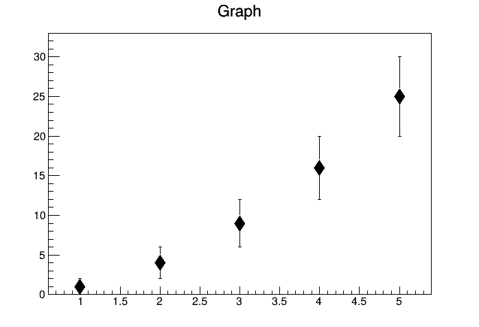
Changing marker size also does not lead to any change—i.e., there is the same “one pixel offset” that I described regardless of the marker size chosen.
For example, here is the result with marker size set to 2:
I tried your example on Mac. I generated 2 outputs: png and pdf.
With that small size the marker in the png output is a bit distorted because there
is not enough pixels to draw properly the diagonals. The PDF is fine because pdf is vector graphics. In both case I do not see any pixel shift.
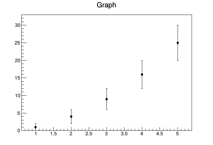
Ok, when I save the plot as a .pdf there is no visible shift for me (see attached), which is helpful. I would still like to figure out why this shift is happening for the raster formats though, especially since it doesn’t seem to be occurring for anyone else?
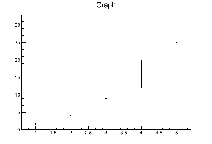
So it seems like this fixes whatever was causing the shift, although strangely it seems like there are now pixels getting cut off on the right hand side of each marker. Possible that that effect is an artifact of distortion due to the limited resolution?
When you generate a raster image in interactive mode a screen dump from what is produced on screen is done. When you run in batch the raster plot is produced via the TASImage package. So, when you see the problem in your raster file, very likely you should see also on your interactive screen output. Given you are running on Ubuntu the screen output is produced by X11. Regarding the “pixels cut off on the right hand side of each marker”, as I said the number of pixel for this marker size is very low, therefore none straight lines rendering is not optimal and (given the low number of pixel available) it is difficult to improve it. I can see several solutions:
keep the size and the marker style but generate vector graphics output (pdf, svg, postscript)
keep the marker style but increase the marker size
keep marker size but use marker a style without oblique lines (there is plenty)