Hello,sir.
About the example of drift tube ,I want to draw two signal figure on one canvas, how should i set the function?
I mean… like the “hold on” in matlab
Can you be a bit more precise ? do you have already some C++ macro ?
The example “drift tube”, which output a figure about signal and time. Now i want to try different position of particle source and put these signal curve on a same canvas(one picture).
I don’t have macro , I just made some modify on the original file…
Hi,
I think I know what you mean. The PlotSignal function of the ViewSignal class has an argument same. If you set it to true, then it will keep the existing plot.
Alternatively, you could just store the signal in a ROOT histogram and make the plot yourself…
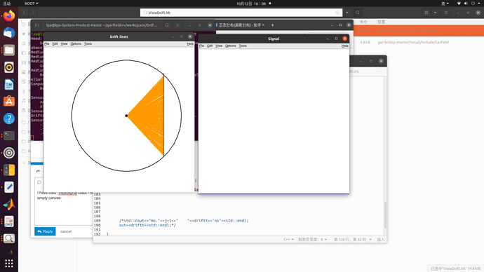
I have tried “ViewSignal class - void PlotSignal - const bool same=true” but finally I got a empty canvas
By the way, how could I store the signal in ROOT histogram?
If you want to draw multiple signals on the same canvas in the drift tube example, you can replace the line
if (plotSignal) signalView.PlotSignal("s");
by
if (plotSignal) {
  if (j == 0) {
   signalView.PlotSignal("s");
  } else {
    signalView.PlotSignal("s", true, false, false, false, true);
  }
}
Assuming you do this in a loop with counter j (like in the drift tube example), you can do something like this to save the signal pulse to a histogram:
std::string hname = "hSignal" + std::to_string(j);
TH1F hSignal(hname.c_str(), "", nbins, tmin, tmin + nbins * tstep);
for (unsigned int k = 0; k < nbins; ++k) {
  hSignal.SetBinContent(k + 1, sensor.GetSignal("s", k));
}
// hSignal.DrawCopy();
That works!
Why I should set the flag to false when j=0 and set the flag to true otherwise.I don’t get the principle, Why couldn’t I set “true” all the time…
About the ROOT histogram. I copy these code to the source code, but …it seems nothing happened.
Does ROOT have some interface or some visuable graph or anything? Actually I know little about ROOT…
Ok, I’ll try to fix that.
Yes, you need to “draw” the histogram to show it. I’ve attached a modified version of the drift tube example…
mdt.C (4.3 KB)
Thank you very much!
One more question. When electrons reach the anode, theoretically only a negative signal is generated, but the output diagram in the example has a positive signal. why…
You’re right, the induced current pulse is indeed negative. The signal shown on the plot is the convolution of the induced current pulse with a bipolar transfer function.
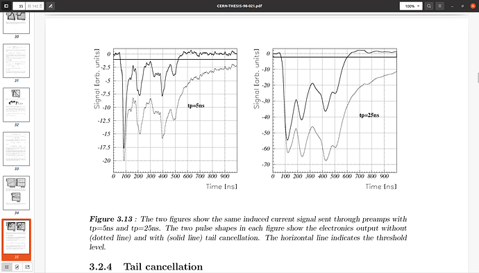
On some reference, the researcher simulated the signal like follow.
Does it mean their result was not convoluted by the transfer function? I have used PlotElectronSignal() however coudn’t get the graph like that. Also, they use “the number of electrons” to describe the value of signal, but GARFIELD use unit fc, whether the program have some opinion to switch it?
Appreciated for your reply!
These two figures were also made by convoluting the induced current with a transfer function.
I don’t know off-hand what model/parameterisation of the transfer function was used in this thesis (and in these two plots in particular) but it might be different from the one we are using in the drift tube example.
There is no pre-implemented option to switch the units from fC to number of electrons but you could do the scaling yourself…
I got it, thank you Mr.
This topic was automatically closed 14 days after the last reply. New replies are no longer allowed.

