Varying thickness TGeoXtru in ROOT Geometry


Dear All,

Could you please guide me on how to use the Xtru geometry volume in the root geometry? I am particularly interested in varying the thickness of Xtru along the Z direction (thickness direction).
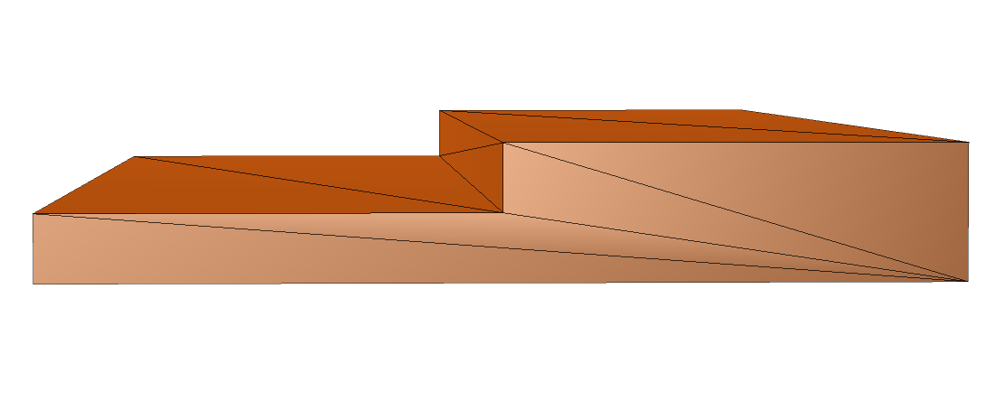
As I understood, the current Xtru available in root can perform, for example: If it is stepped like above, then:

<solids>

    <xtru name="SteppedThicknessXtruShape" lunit="cm">

      <twoDimVertex x="0" y="-0.75"/>

      <twoDimVertex x="10" y="-0.75"/>

      <twoDimVertex x="10" y="0.75"/>

      <twoDimVertex x="5" y="0.75"/>

      <twoDimVertex x="5" y="0"/>

      <twoDimVertex x="0" y="0"/>

      <section zOrder="0" zPosition="-10" xOffset="0" yOffset="0" scalingFactor="1"/>

      <section zOrder="1" zPosition="10" xOffset="0" yOffset="0" scalingFactor="1"/>

    </xtru>

  </solids> 

or
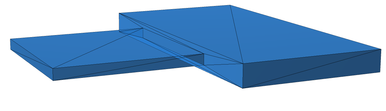
<solids>

    <xtru name="SectionScaledXtruShape" lunit="cm">

      <twoDimVertex x="-10" y="-0.75"/>

      <twoDimVertex x="10" y="-0.75"/>

      <twoDimVertex x="10" y="0.75"/>

      <twoDimVertex x="-10" y="0.75"/>

      <section zOrder="0" zPosition="-10" xOffset="0" yOffset="0" scalingFactor="0.5"/>

      <section zOrder="1" zPosition="-0.02" xOffset="0" yOffset="0" scalingFactor="0.5"/>

      <section zOrder="2" zPosition="0.02" xOffset="0" yOffset="0" scalingFactor="1"/>

      <section zOrder="3" zPosition="10" xOffset="0" yOffset="0" scalingFactor="1"/>

    </xtru>

  </solids> 

This means TGeoXtru can represent:

  • a straight extrusion;

  • a globally tapered extrusion;

  • an extrusion that shifts in X or Y;

  • an abrupt change between two globally scaled profiles using repeated Z sections.

However, how is it possible to represent geometry for a varying thickness, a case when

  • only one local region becomes thinner;

  • selected vertices moving while other vertices remain fixed;

meaning a change in polygon topology.

Because for standard TGeoXtru, changing scale changes every vertex.

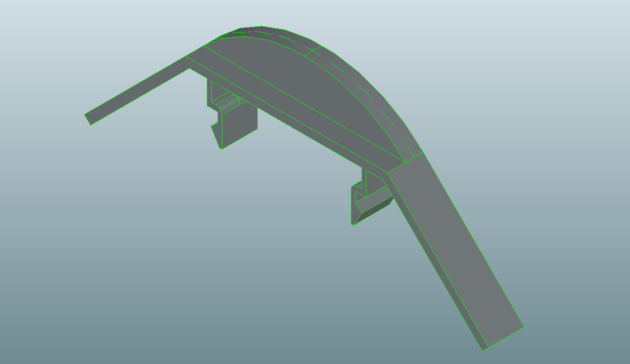
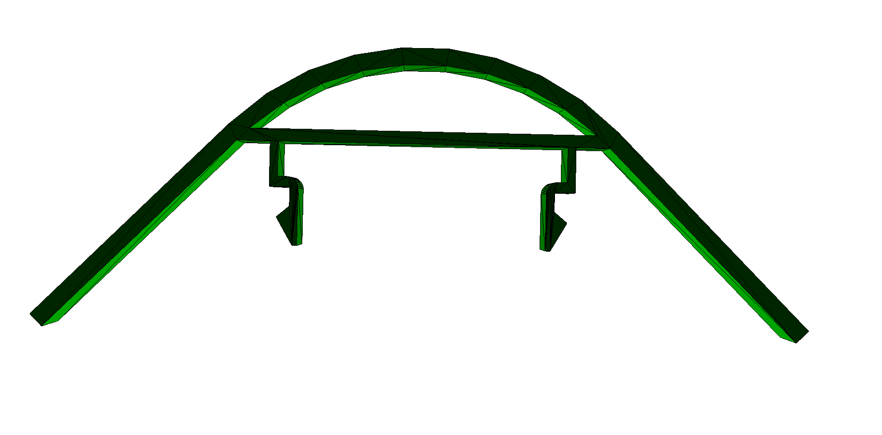
Actually, I wanted to build a geometry volume like shown below as a single Xtru volume.
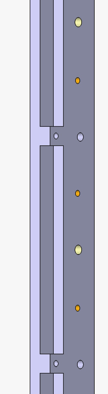
and from the back
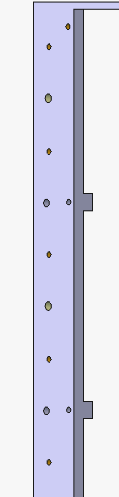
Could you please guide me on how it can be possible?

Thank you.
Hello @mehul,

I will refer this to @agheata as the geometry expert.

Hi @mehul, TGeoXtru only offers a polygonal “blueprint” that can only be scaled and/or shifted, it does not allow to change the shape/vertices at different sections. For what you want, it looks like you should use either multiple volumes positioned adjacent to each other, or use Boolean subtractions. TGeoXtru is not appropriate for that.

@agheata As mentioned, on a CERN ROOT geometry, this CSG (composite solid geometry) hierarchy is effective for a small number of components, but performance drops dramatically for large structures. Building a complete geometry in this style is virtually possible but highly not recommended.

Apart from the above, actually, what I am trying to do is reverse-engineer the primitive solid-based geometry to use in the simulation. By reverse-engineering here, I mean converting the geometry into a mesh from a CAD tool and saving the information as a tessellated solid in a GDML file.
Once this is done, we can read the resulting GDML file containing tessellated solid information, and the volume can be represented as a tessellated solid. However, as you already know, for large simulation geometries, this is not a good option because it requires significant memory and increases event transport time. Thus, to avoid a bottleneck problem with the tessellated solid;

I have learned that, from tessellated mesh vertex information, one can reconstruct the geometry into primitive solids again by obtaining valid polygonal information using algorithms such as Silhouette and the Douglas-Peucker algorithm, which are commonly used in computer graphics.

In ROOT geometry representation, there are two geometrical shapes, TGeoXtru and TGeoArb8, which can be built using twodimvertex between Zmin and Zmax.

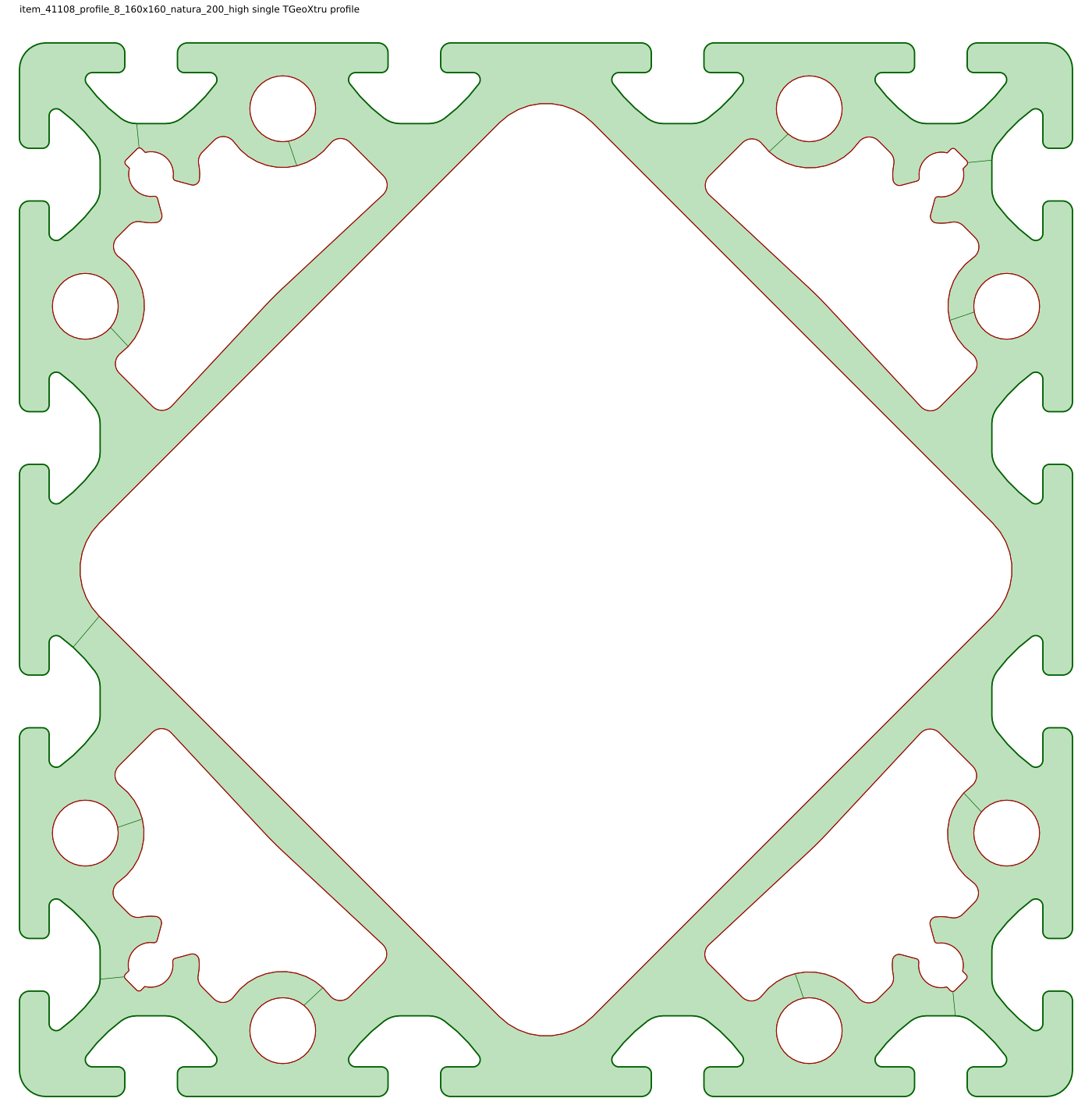
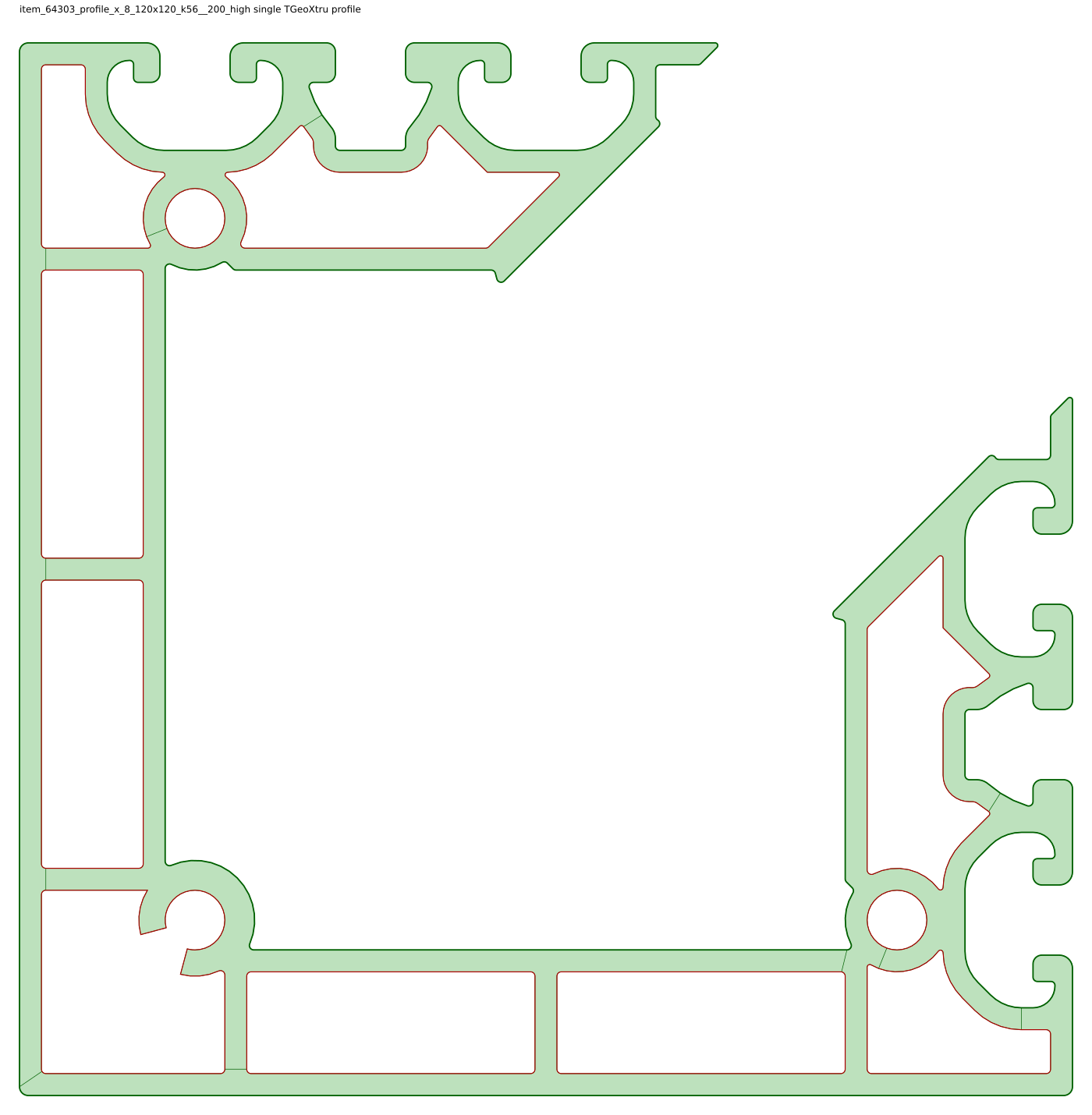
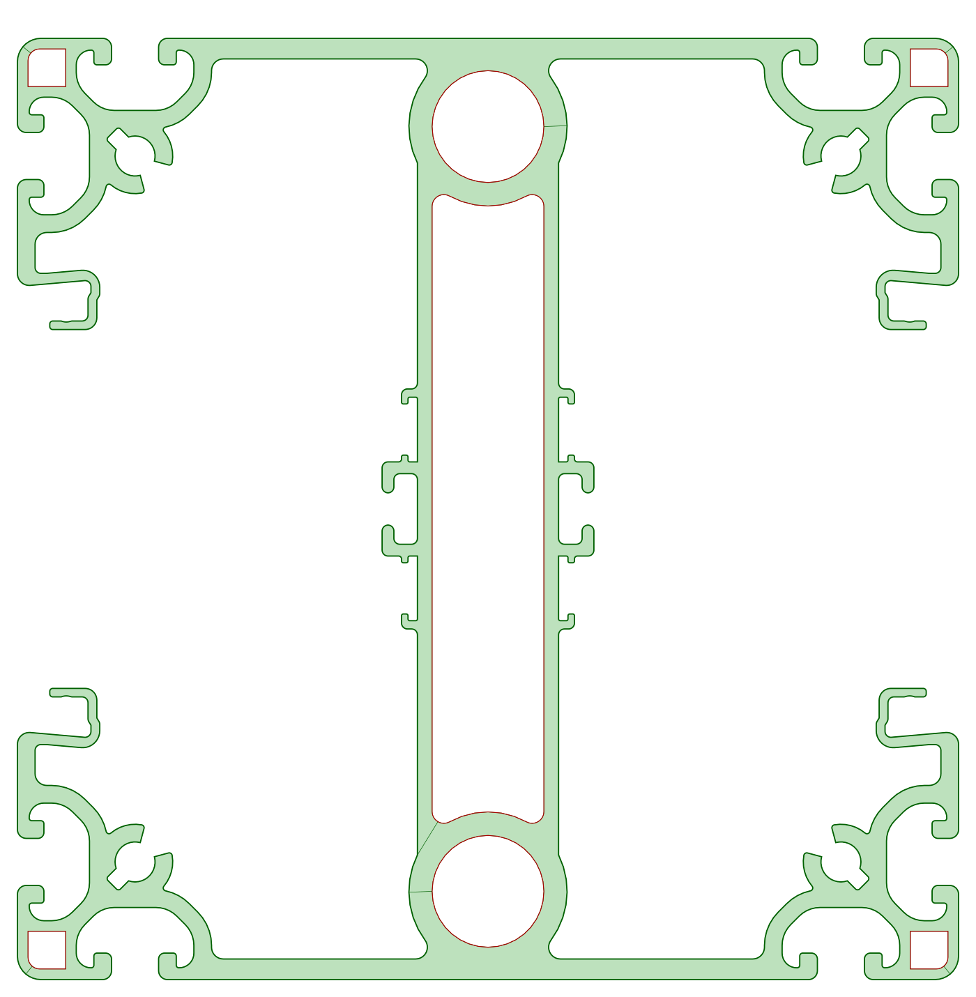
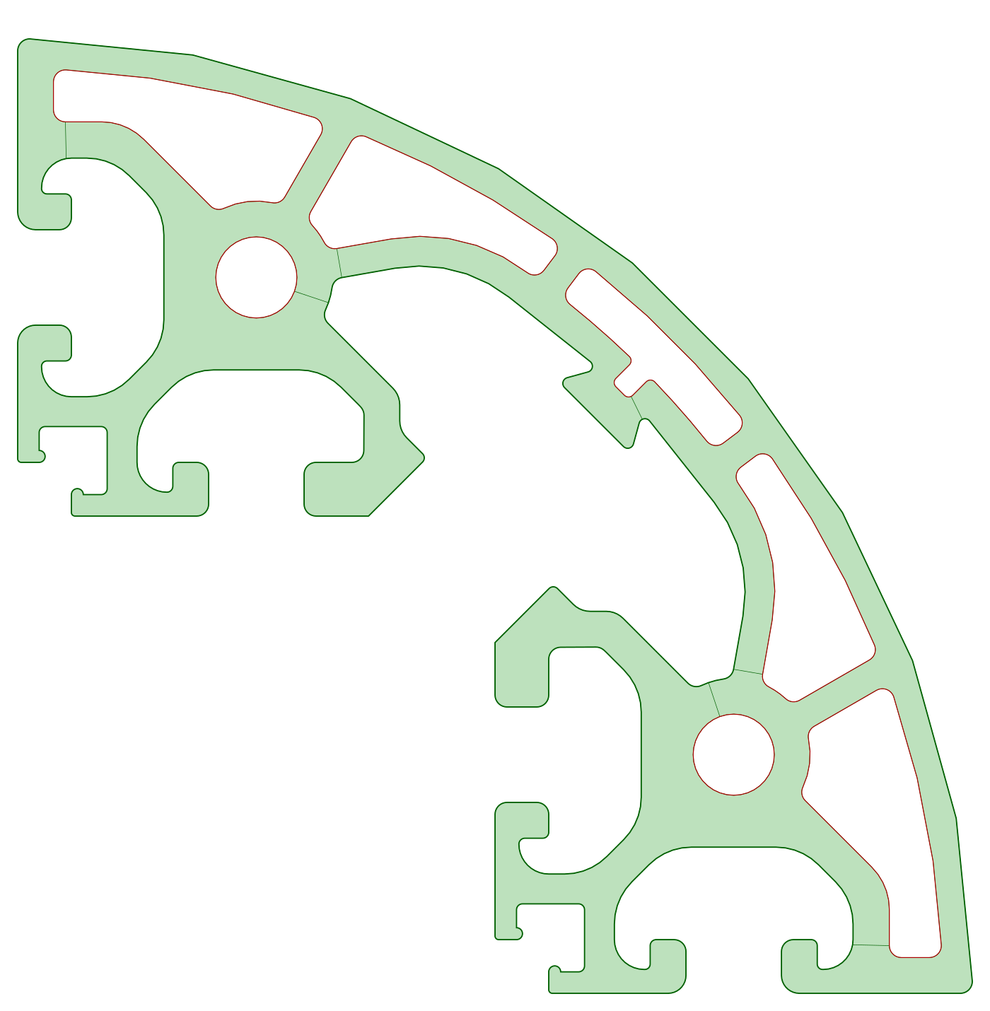
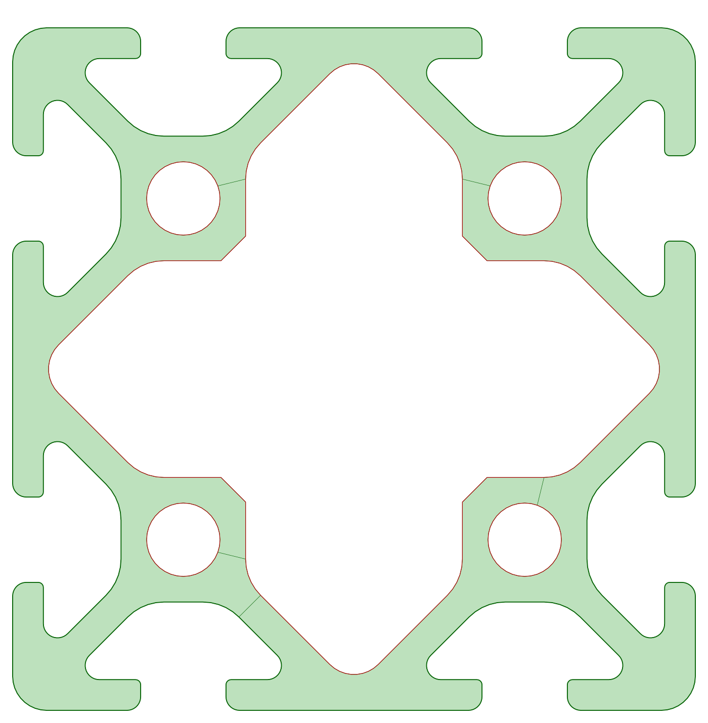
I have tried out the reverse-engineering concept with different ItemProfile to form a TGeoXtru ROOT geometry representation, as you can see in the image below.

Since the shown item profile had a constant Z order, reconstruction was done properly, but when I tried to do it with the varying-thickness objects, as you can see below, it could not do it properly, and the parts that were constant Z order, the part where the vertex point was changing in a thickness direction, couldn’t be reconstructed.

This is, I think, because in the current TGeoXtru, for every polygonal blueprint it stores only
z[k], x0[k], y0[k], scale[k]
and changing scale changes every vertex, so it does not represent an arbitrarily varying section solid. Otherwise, a varying-thickness part can currently be constructed as a separate volume and added to a TGeoVolumeAssembly along with the main volume.

So the question is how, and which parts of the TGeoXtru.cxx and .h files need to be changed to account for these varying-thickness vertex points so that both constant Z order and varying Z order can be represented as a single Xtru?

Thank you.

Generalizing simple shapes to add more features in order to support a more complex case is not a good idea. In particular for your use case, the assembly option seems more appropriate. However, you should note that for the very complex profiles you are using, TGeoXtru is not necessary the fastest option for simulation, because the navigation scales linearly with the number of vertices. The most recent ROOT release supports BVH-accelerated TGeoTessellated, so you should rather try to convert these profiles to tessellations.

Hi @agheata , many thanks. :smiley: