Hello,
I am working on simulating a spherical proportional counter with a thin wire anode (made thicker for the pictures). My current approach is outlined below. At first, I thought this was a reasonable way, but looking back, I am not entirely sure if my way of defining the counter is sensible, as i struck multiple problems. So, I would like to ask for a feedback before I move on to the particle stimuli.
Does my approach make sense, or is there a better way to define the counter?
Could I have unintentionally broken something while modifying the Garfield++ source code?
Thank you very much in advance for any feedback or advice.
I defined a 2D cross-section of the counter in the XY plane using Gmsh and simulated the electric field with ElmerFEM. I decided not to simulate the full 3D volume, as that would understandably take much longer to compute.
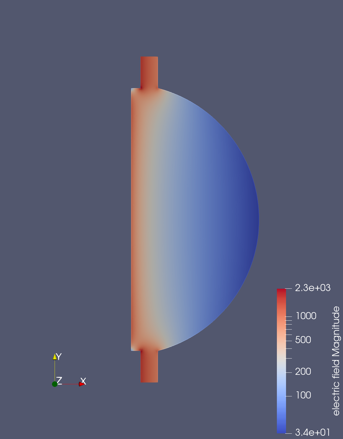
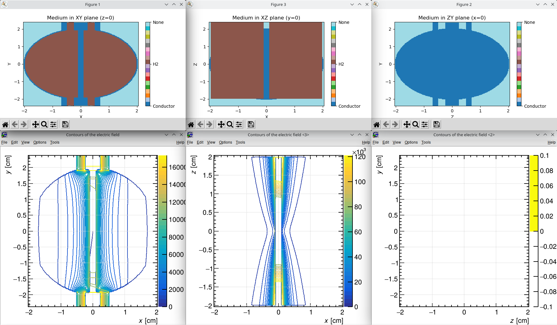
In Garfield++, I used the ComponentElmer2d class to load the field and expected to obtain a full 3D representation by enabling rotational symmetry around the Y-axis. However, when plotting the geometry and the field in all three base planes, I noticed that the result was incorrect: instead of producing the expected rotational symmetry, it merely mirrored the field in the XY plane and “extruded” it along the Z-axis.
Therefore, I examined the Garfield++ source code and found that in the ComponentFieldMap class, there is a code intended to map the 2D field in the expected rotational way. However, this code is ineffective because the m_is3d flag is set to false in ComponentElmer2d. To address this, I defined a wrapper class as follows:
namespace Garfield {
    class MyComponentElmer2d3d : public ComponentElmer2d {
    public:
        // Constructor that overwrites m_is3d
        MyComponentElmer2d3d() {
            m_is3d = true;
        }

        void fixRanges() {
            m_mapmin[0] = -m_mapmax[0];
            m_mapmin[2] = -m_mapmax[0];
            m_mapmax[2] =  m_mapmax[0];
        }
    };
}
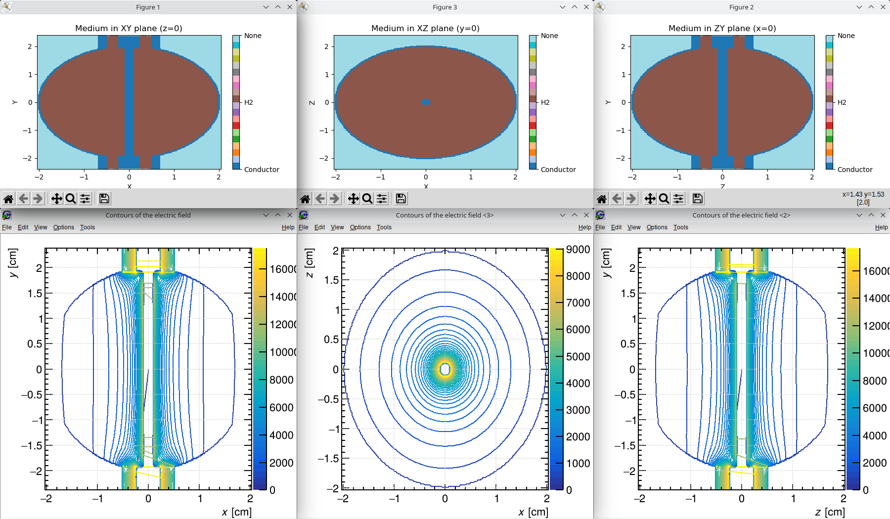
This seemed to do the trick, as the geometry generated with this component looks as expected.
However, one final issue arose: the vectors of the electric field were not rotated correctly. They always pointed in the +X direction rather than radially outward from the anode wire (something that is not evident from the magnitude plots shown above). I resolved this by modifying the coordinates passed to the UnmapFields function in ComponentFieldMap.cc (line 196), using the original coordinates instead of those modified by the previous MapCoordinates function call:
UnmapFields(fx, fy, fz, xin, yin, zin, xmirr, ymirr, zmirr, rcoordinate, rotation);
This finally resulted in the expected field, as illustrated by the X component shown here.
