Problems in simulation of drift chamber

Hello,
I am trying to simulate a drift chamber, but I am facing some issues:

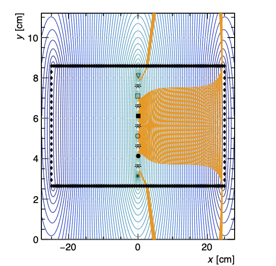
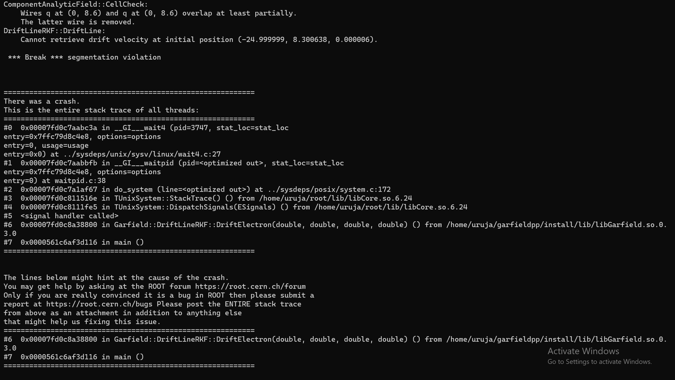
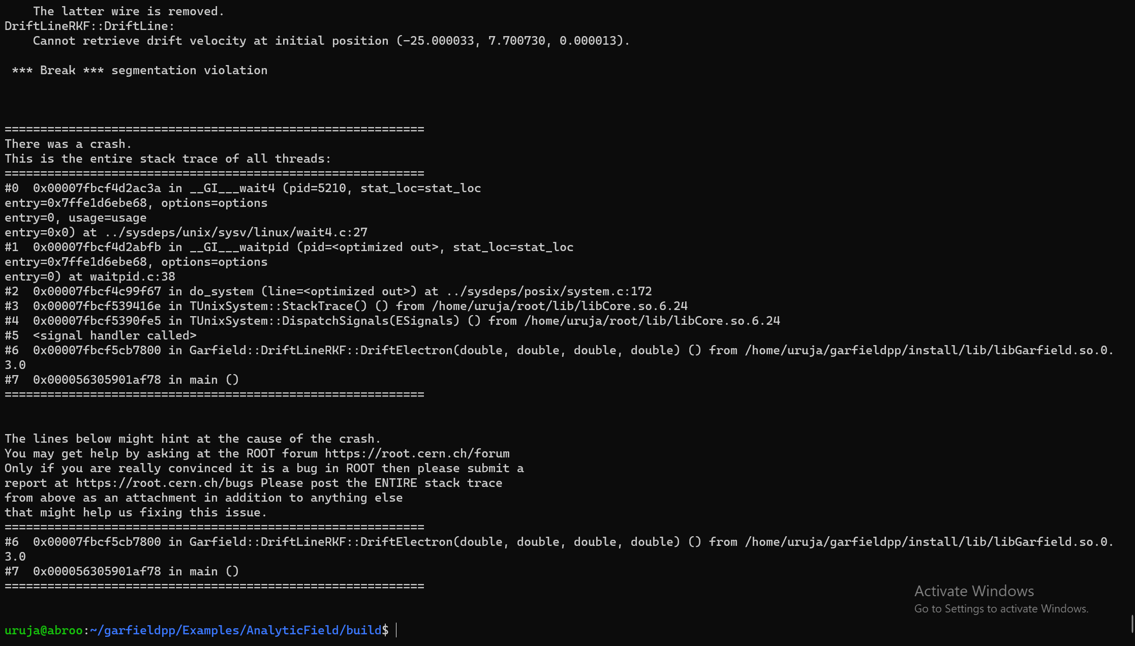
  1. The guard wires are not producing any drift lines.
  2. Some drift lines lie outside the chamber geometry.

The code I am using:

#include <iostream>
#include <cstdlib>
#include <math.h>
#include <fstream>

#include <TCanvas.h>
#include <TROOT.h>
#include <TApplication.h>

#include "Garfield/ViewField.hh"
#include "Garfield/ViewCell.hh"
#include "Garfield/ComponentAnalyticField.hh"
#include "Garfield/MediumMagboltz.hh"
#include "Garfield/Plotting.hh"

#include "Garfield/GeometrySimple.hh"
#include "Garfield/SolidBox.hh"
#include "Garfield/ViewSignal.hh"

#include "Garfield/DriftLineRKF.hh"
#include "Garfield/TrackHeed.hh"
#include "Garfield/Sensor.hh"
#include "Garfield/ViewDrift.hh"
#include "Garfield/AvalancheMicroscopic.hh"
#include "Garfield/AvalancheMC.hh"
#include "Garfield/ViewMedium.hh"

#include "Garfield/ViewGeometry.hh"


#include <TH1F.h>
#include <TH2F.h>


#define PI 3.14159265

using namespace Garfield;
using namespace std;
double transfer(double t) {
const double tau = 61.1;// time constant
return exp(- t / tau);
}
int main(int argc, char * argv[]) {

  TApplication app("app", &argc, argv);
  
  plottingEngine.SetDefaultStyle();

// Gas mixture.
  MediumMagboltz gas;
  gas.LoadGasFile("ar_94_co2_6.gas");
  const string path = getenv("GARFIELD_INSTALL");
  gas.LoadIonMobility(path + "/share/Garfield/Data/IonMobility_Ar+_Ar.txt");
 
  
 // Create the geometry.
   GeometrySimple( geo);
  
    
  SolidBox* chamber = new SolidBox(0,11.2/2,400.0/2,50.8/2,11.2/2,400.0/2);
  geo.AddSolid(chamber, &gas);

  ComponentAnalyticField cmp;
  cmp.SetMedium(&gas);
  cmp.SetGeometry(&geo);

  
  // Wire diameters [cm].
  constexpr double ds = 0.006400; // sense wires
  constexpr double dc = 0.0200000; // cathode wires
  constexpr double dg = 0.0200000; // gate wires
  constexpr double df = 0.0200000; // field forming wires

  // Voltage settings [V].
  constexpr double vs = 2200.; // sense wires
  constexpr double vg = 2200;  // gate wires
  constexpr double vc = 0000.;  // cathode wires


  // Add the sense (anode) wires.
  float x_wires[4] = {0.075,-0.075,0.075,-0.075};
  float z_wires[4] = {4.10,5.10,6.10,7.10};
  
   cmp.AddWire(x_wires[0], z_wires[0], ds, vs, "s1", 370);
  cmp.AddReadout("s1");
  cmp.AddWire(x_wires[1], z_wires[1], ds, vs, "s2", 370);
  cmp.AddReadout("s2");
  cmp.AddWire(x_wires[2], z_wires[2], ds, vs, "s3", 370);
  cmp.AddReadout("s3");
  cmp.AddWire(x_wires[3], z_wires[3], ds, vs, "s4", 370);
  cmp.AddReadout("s4");
  // Add the cathode wires.

  for (int i=0;i<5;i++){
 cmp.AddWire(0.3, 3.6+1.0*i, dc, vc, "c", 400);
 cmp.AddWire(-0.3, 3.6+1.0*i, dc, vc, "c", 400);
}
 cmp.AddReadout("c");
 
  // Add the gate wires.
  constexpr double yg1 = 3.10;
  constexpr double yg2 = 8.10;//5 * period;
  constexpr double xg1 =-0.075;// 2. * gap + 0.3;
  constexpr double xg2 =0.075;
  cmp.AddWire(xg1, yg1, dg, vg, "g1", 370);  
  cmp.AddWire(xg2, yg2, dg, vg, "g2", 370); 
  cmp.AddReadout("g1");
  cmp.AddReadout("g2"); 


  for (int i=0;i<50;i++){
  cmp.AddWire(0+0.5*i, 5.6-3.0, 0.02, -250*i, "q", 400);
  cmp.AddWire(0+0.5*i, 5.6+3.0, 0.02, -250*i, "q", 400);
  
  cmp.AddWire(0-0.5*i, 5.6-3.0, 0.02, -250*i, "q", 400);
  cmp.AddWire(0-0.5*i, 5.6+3.0, 0.02, -250*i, "q", 400);

 }


  for (int i=0;i<21;i++){
  cmp.AddWire(-25, 5.6-3.0+0.3*i, 0.02, -12000, "q", 400);
  cmp.AddWire( 25, 5.6-3.0+0.3*i, 0.02, -12000, "q", 400);
  }
  // Make a sensor.
  cmp.AddReadout("q");
  // Calculate the electric field using the Component object cmp.
  Sensor sensor;
  sensor.AddComponent(&cmp);
  sensor.AddElectrode(&cmp, "s1");
  sensor.AddElectrode(&cmp, "s2");
  sensor.AddElectrode(&cmp, "s3");
  sensor.AddElectrode(&cmp, "s4");
  sensor.AddElectrode(&cmp, "g1");
  sensor.AddElectrode(&cmp, "g2");
  sensor.AddElectrode(&cmp, "c");
  sensor.AddElectrode(&cmp, "q");

 const double tstep = 1;//0.5;
  const double tmin = 0;//-0.5 * tstep;
  const unsigned int nbins = 6000;
  sensor.SetTimeWindow(tmin, tstep, nbins);

ViewDrift driftView;
  driftView.SetArea(-50.,-12,-400,50,12,400); 

  
  TrackHeed track;
  track.EnablePlotting(&driftView);

  track.SetParticle("muon");
  track.SetEnergy(1.e9);//170.e9);
  track.SetSensor(&sensor);

 for (int a =0;a<1;a++)//Events
 {
 DriftLineRKF drift;
  drift.SetSensor(&sensor);
 drift.EnableSignalCalculation();
 drift.EnablePlotting(&driftView);
 sensor.SetTransferFunction(transfer);
sensor.ClearSignal();
  sensor.NewSignal();
{ 
        track.NewTrack(double(a), 11.2, 0, double(a), double(a), -11.2, 0); //b_pos_x
          // Loop over the clusters along the track.
        double xc = 0., yc = 0., zc = 0., tc = 0., ec = 0., extra = 0.;
        int nc = 0;
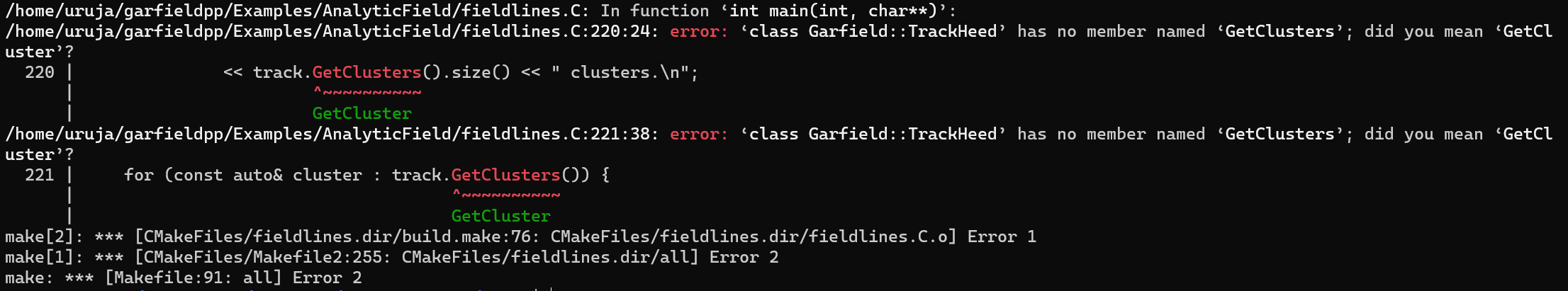
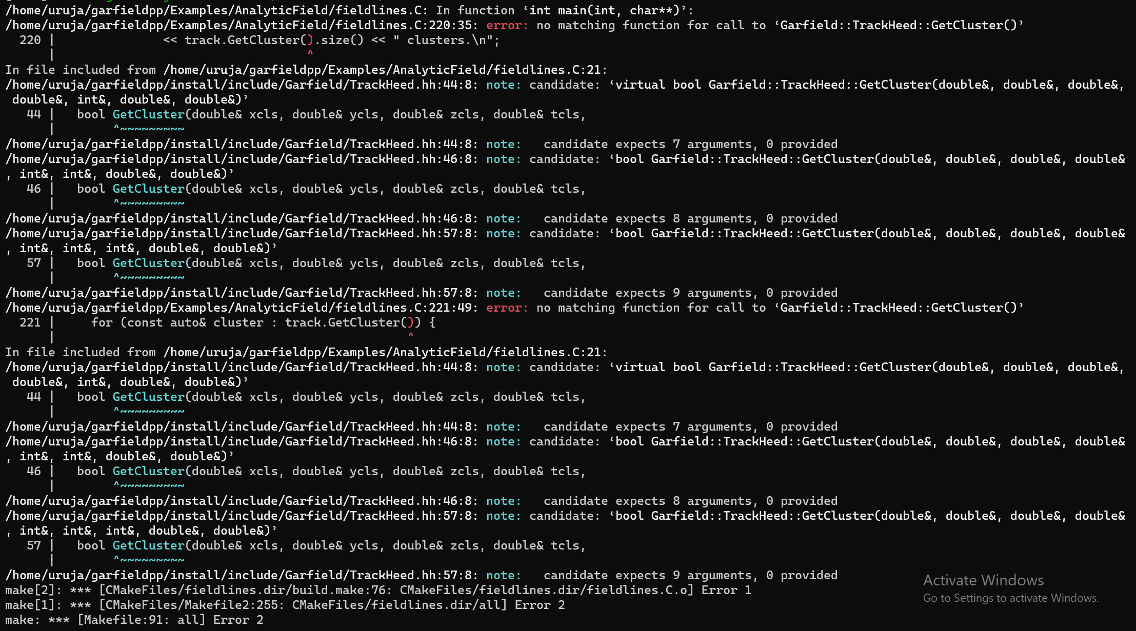
        while (track.GetCluster(xc, yc, zc, tc, nc, ec, extra)) {
     // Loop over the electrons in the cluster.
        for (int k = 0; k < nc; ++k) {
        double xe = 0., ye = 0., ze = 0., te = 0., ee = 0.;
        double dx = 0., dy = 0., dz = 0.;
        track.GetElectron(k, xe, ye, ze, te, ee, dx, dy, dz);
        drift.DriftElectron(xe, ye, ze, te);
  }
     }

 }
ViewSignal signalView;
  signalView.SetSensor(&sensor);
sensor.ConvoluteSignal("s1",false);
  TCanvas* S1 = new TCanvas("s1","s1",1600,800);
  signalView.SetCanvas(S1);
  signalView.PlotSignal("s1");
  S1->SaveAs("S1.png");

  sensor.ConvoluteSignal("s2",false);
  TCanvas* S2 = new TCanvas("s2","s2",1600,800);
  signalView.SetCanvas(S2);
  signalView.PlotSignal("s2");
  S2->SaveAs("S2.png");

  sensor.ConvoluteSignal("s3",false);
  TCanvas* S3 = new TCanvas("s3","s3",1600,800);
  signalView.SetCanvas(S3);
  signalView.PlotSignal("s3");
  S3->SaveAs("S3.png");

 sensor.ConvoluteSignal("s4",false);
  TCanvas* S4 = new TCanvas("s4","s4",1600,800);
  signalView.SetCanvas(S4);
  signalView.PlotSignal("s4");
  S4->SaveAs("S4.png");

  ViewCell cellView;
  TCanvas* myCanvas = new TCanvas();
  cellView.SetComponent(&cmp);
  cellView.SetArea(-50.8 / 2., -11.2/2,-400/2, 50.8 / 2., 11.2,400);
  cellView.SetCanvas(myCanvas);
  cellView.Plot2d();

  driftView.SetCanvas(myCanvas);
  driftView.Plot(true, false);
        myCanvas->SaveAs("drift.png");
}
ViewField fieldView;
  fieldView.SetComponent(&cmp);
fieldView.SetArea(-55.8/2, 0, 55.8/2, 11.2);
  fieldView.SetVoltageRange(-12000., 14200.);
  fieldView.SetNumberOfContours(100);
fieldView.Plot("v", "CONT1"); 
  // Plot field lines.
  vector<double> xf;
  vector<double> yf;
  vector<double> zf;
  
  fieldView.EqualFluxIntervals(48.8/2,-0.5,0, 48.8/2, 11.2, 0.,
                              xf, yf, zf, 100);
fieldView.PlotFieldLines(xf, yf, zf, true, false); 

  // Plot the cell layout.
  //ViewCell cellView;
  cellView.SetCanvas(fieldView.GetCanvas());
  
  cellView.SetComponent(&cmp);
  //cellView.SetArea(-50.8/2,-11.2, 50.8/2, 11.2);
  cellView.Plot2d();


 app.Run(true);


}

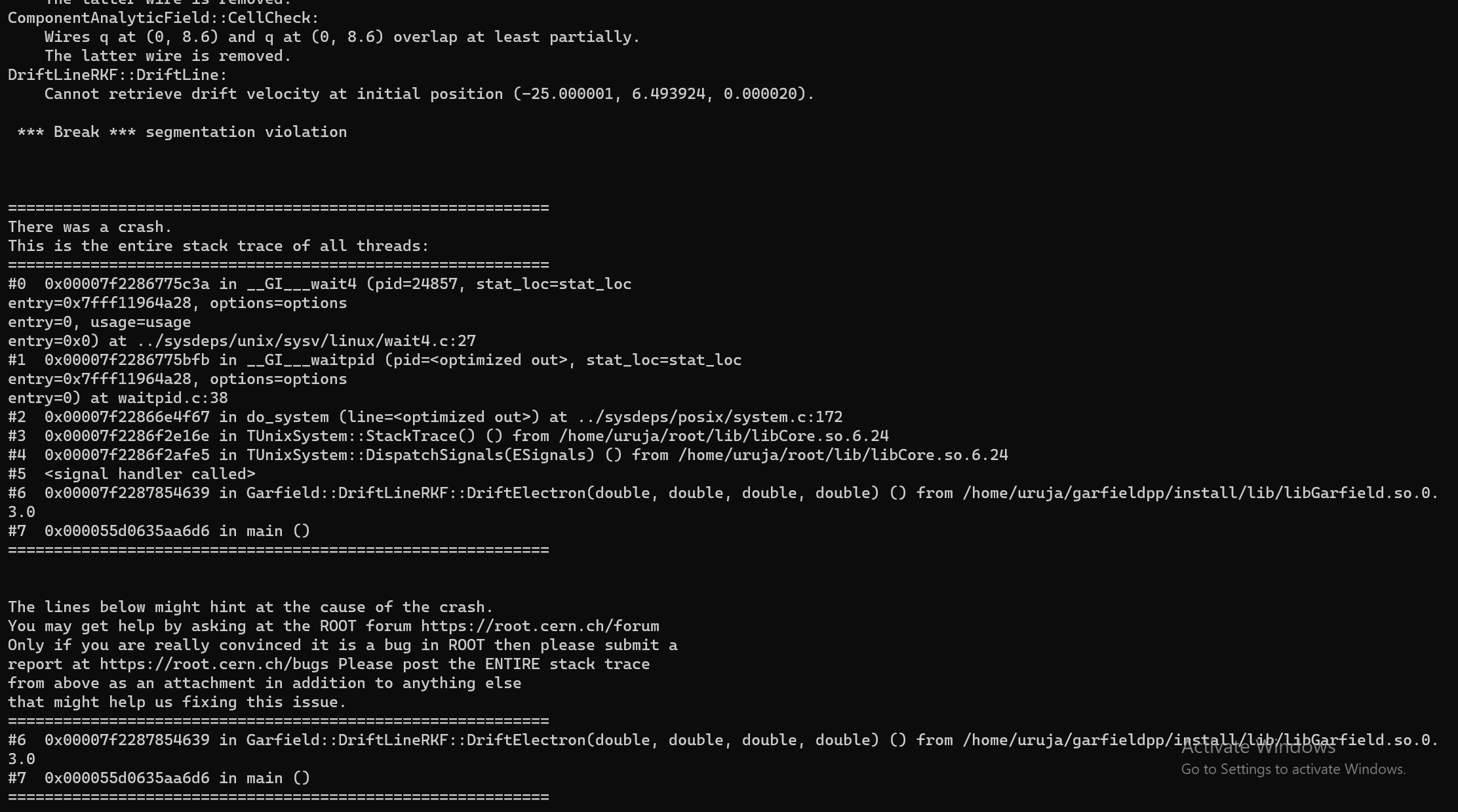
This are the outputs I am getting when I am considering only one event:

image

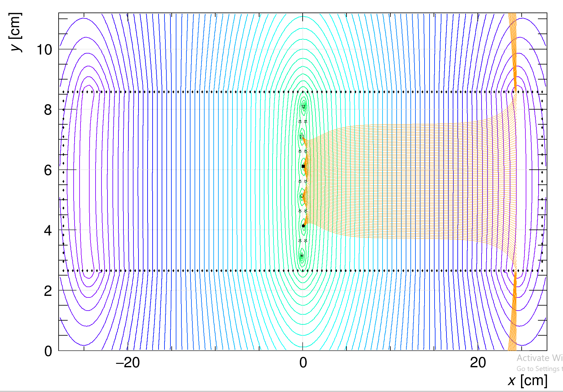
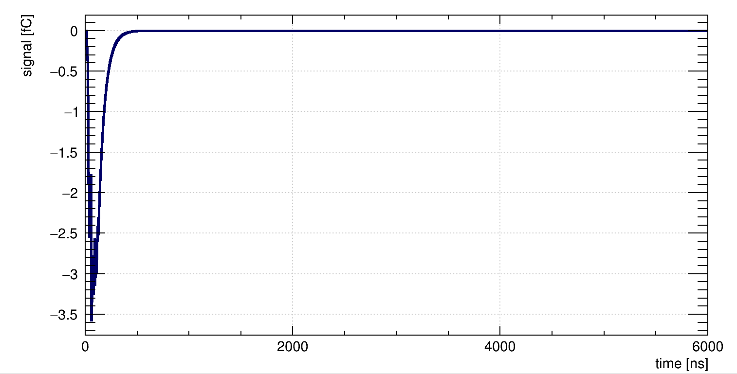
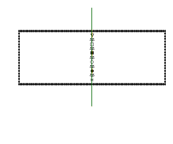
Please help me solve these issues.

Hi,
I’ve not yet ready the code you sent in detail, but just a quick question: would you actually expect the electron drift lines to go to the guard wires in your layout?

Yes. They have the same configuration as sense wires. So, they should have drift line.

Also, I changed my code a little. I increased the number of events and changed the track.NewTrack line as follows:

...
for (int a =-25;a<25;a++)
.....
track.NewTrack(double(a), 11.2, 0, 0, double(0.1), -11.2, 0);

.....

Now I have two more issues:

  1. Why does segmentation violation come up when I use 0 instead of 0.1 in the x coordinate of initial direction of particles in this line? I basically want vertical tracks. The output in the console is as follows:

  2. When I just use the track.NewTrack line as shown above the program run well for some iterations and then throws up the following error continuously:

What is the problem? Please help me

If I increase the range of the active area towards the bottom and top (using the slightly modified, “minimal” version of your example below), I seem to get some drift lines that end up on the “g1” and “g2” wires.

  MediumMagboltz gas;
 
  ComponentAnalyticField cmp;
  cmp.SetMedium(&gas);
  
  // Wire diameters [cm].
  constexpr double ds = 0.006400; // sense wires
  constexpr double dc = 0.0200000; // cathode wires
  constexpr double dg = 0.0200000; // gate wires
  constexpr double df = 0.0200000; // field forming wires

  // Voltage settings [V].
  constexpr double vs = 2200.; // sense wires
  constexpr double vg = 2200;  // gate wires
  constexpr double vc = 0000.;  // cathode wires
  
  // Add the sense (anode) wires.
  float x_wires[4] = {0.075, -0.075, 0.075, -0.075};
  float z_wires[4] = {4.10, 5.10, 6.10, 7.10};
  
  cmp.AddWire(x_wires[0], z_wires[0], ds, vs, "s1", 370);
  cmp.AddWire(x_wires[1], z_wires[1], ds, vs, "s2", 370);
  cmp.AddWire(x_wires[2], z_wires[2], ds, vs, "s3", 370);
  cmp.AddWire(x_wires[3], z_wires[3], ds, vs, "s4", 370);

  // Add the cathode wires.
  for (int i = 0; i < 5; i++){
    cmp.AddWire( 0.3, 3.6 + 1.0 * i, dc, vc, "c", 400);
    cmp.AddWire(-0.3, 3.6 + 1.0 * i, dc, vc, "c", 400);
  }
 
  // Add the gate wires.
  constexpr double yg1 = 3.10;
  constexpr double yg2 = 8.10;//5 * period;
  constexpr double xg1 =-0.075;// 2. * gap + 0.3;
  constexpr double xg2 =0.075;
  cmp.AddWire(xg1, yg1, dg, vg, "g1", 370);
  cmp.AddWire(xg2, yg2, dg, vg, "g2", 370);

  for (int i = 0; i < 50; ++i) {
    cmp.AddWire(0.5*i, 5.6-3.0, 0.02, -250*i, "q", 400);
    cmp.AddWire(0.5*i, 5.6+3.0, 0.02, -250*i, "q", 400);
  
    cmp.AddWire(-0.5*i, 5.6-3.0, 0.02, -250*i, "q", 400);
    cmp.AddWire(-0.5*i, 5.6+3.0, 0.02, -250*i, "q", 400);
  }

  for (int i = 0; i < 21; ++i) {
    cmp.AddWire(-25, 5.6-3.0+0.3*i, 0.02, -12000, "q", 400);
    cmp.AddWire( 25, 5.6-3.0+0.3*i, 0.02, -12000, "q", 400);
  }

  ViewField fieldView;
  fieldView.SetComponent(&cmp);
  fieldView.SetArea(-55.8/2, 0, 55.8/2, 11.2);
  fieldView.SetVoltageRange(-12000., 14200.);
  fieldView.SetNumberOfContours(100);
  fieldView.Plot("v", "CONT1"); 
  // Plot field lines.
  vector<double> xf;
  vector<double> yf;
  vector<double> zf;
  
  fieldView.EqualFluxIntervals(48.8/2,-0.5,0, 48.8/2, 11.2, 0.,
                               xf, yf, zf, 100);
  fieldView.PlotFieldLines(xf, yf, zf, true, false); 

  // Plot the cell layout.
  ViewCell cellView;
  cellView.SetCanvas(fieldView.GetCanvas());
  cellView.SetArea(-55.8/2, 0, 55.8/2, 11.2);
  cellView.SetComponent(&cmp);
  cellView.Plot2d();

  app.Run(true);
``

Why are the guard wires behaving so differently? I want them to behave very similar to the signal wires like this:

What are the voltage settings of the array of wires surrounding the cell in this plot? Are they identical to the ones in your example?

yes. Voltage of the surrounding wires are same i.e 0V near the centre and progressively go on becoming more negative until the wires in the left and right extreme become -12kv

It seems the second problem here was related to my graphic driver. So I just removed the part of the code that plots the signals in every iteration and instead saved the signals in test file using sensor.GetSignal (). So this error is resolved. i.e.

But still the segmentation violation I am not able to sove.

I’m not sure what could have caused the segmentation violation but here is a slightly modified version of the part of your code that simulates drift lines from a charged particle track which works fine for me:

  // Gas mixture.
  MediumMagboltz gas;
  gas.LoadGasFile("ar_80_co2_20_0T.gas");
  // gas.LoadGasFile("ar_94_co2_6.gas");
 
  ComponentAnalyticField cmp;
  cmp.SetMedium(&gas);
  
  // Wire diameters [cm].
  constexpr double ds = 0.006400;  // sense wires
  constexpr double dc = 0.0200000; // cathode wires
  constexpr double dg = 0.0200000; // gate wires

  // Voltage settings [V].
  constexpr double vs = 2200.; // sense wires
  constexpr double vg = 2200;  // gate wires
  constexpr double vc = 0000.; // cathode wires
  
  // Add the sense (anode) wires.
  float x_wires[4] = {0.075, -0.075, 0.075, -0.075};
  float z_wires[4] = {4.10, 5.10, 6.10, 7.10};
  
  cmp.AddWire(x_wires[0], z_wires[0], ds, vs, "s1", 370);
  cmp.AddWire(x_wires[1], z_wires[1], ds, vs, "s2", 370);
  cmp.AddWire(x_wires[2], z_wires[2], ds, vs, "s3", 370);
  cmp.AddWire(x_wires[3], z_wires[3], ds, vs, "s4", 370);

  // Add the cathode wires.
  for (int i = 0; i < 5; ++i) {
    cmp.AddWire( 0.3, 3.6+1.0*i, dc, vc, "c", 400);
    cmp.AddWire(-0.3, 3.6+1.0*i, dc, vc, "c", 400);
  }
 
  // Add the gate wires.
  constexpr double yg1 = 3.10;
  constexpr double yg2 = 8.10;
  constexpr double xg1 =-0.075;
  constexpr double xg2 = 0.075;
  cmp.AddWire(xg1, yg1, dg, vg, "g1", 370);  
  cmp.AddWire(xg2, yg2, dg, vg, "g2", 370); 
  cmp.AddReadout("g1");
  cmp.AddReadout("g2"); 

  for (int i = 0; i < 50; ++i) {
    cmp.AddWire(0+0.5*i, 5.6-3.0, 0.02, -250*i, "q", 400);
    cmp.AddWire(0+0.5*i, 5.6+3.0, 0.02, -250*i, "q", 400);
    cmp.AddWire(0-0.5*i, 5.6-3.0, 0.02, -250*i, "q", 400);
    cmp.AddWire(0-0.5*i, 5.6+3.0, 0.02, -250*i, "q", 400);
  }

  for (int i = 0; i < 21; ++i) {
    cmp.AddWire(-25, 5.6-3.0+0.3*i, 0.02, -12000, "q", 400);
    cmp.AddWire( 25, 5.6-3.0+0.3*i, 0.02, -12000, "q", 400);
  }

  Sensor sensor;
  sensor.AddComponent(&cmp);
  const double xmin = -25.1;
  const double xmax =  25.1;
  const double ymin = 2.5;
  const double ymax = 8.7; 
  const double zmin = -100.;
  const double zmax = +100.;
  sensor.SetArea(xmin, ymin, zmin, xmax, ymax, zmax);

  ViewDrift driftView;
  
  TrackHeed track;
  track.EnablePlotting(&driftView);

  track.SetParticle("muon");
  track.SetEnergy(1.e9);
  track.SetSensor(&sensor);

  for (int a = -25; a < 25; a++) {
    DriftLineRKF drift;
    drift.SetSensor(&sensor);
    drift.EnablePlotting(&driftView);
    track.NewTrack(double(a), ymax, 0, 0, 0, -1, 0);
    // Loop over the clusters along the track.
    std::cout << "a = " << a << ": " 
              << track.GetClusters().size() << " clusters.\n";
    for (const auto& cluster : track.GetClusters()) {
      for (const auto& electron : cluster.electrons) {
        drift.DriftElectron(electron.x, electron.y, electron.z, electron.t);
      }
    }
  }

  ViewCell cellView;
  TCanvas* myCanvas = new TCanvas();
  cellView.SetComponent(&cmp);
  cellView.SetArea(xmin, ymin, zmin, xmax, ymax, zmax);
  cellView.SetCanvas(myCanvas);
  cellView.Plot2d();

  driftView.SetCanvas(myCanvas);
  driftView.Plot(true, false);
  myCanvas->SaveAs("drift.png");

This is the error I am getting when I use your modified code:


And if I change the track.GetClusters to track.GetCluster following the suggestion in the error, this is the error I am getting:

Can you upgrade to the latest version of the project (git pull and rebuild)?

I updated using git pull and build the project again. Now I am getting this:

This is not the program I sent you.

Is there any mistake:

#include <iostream>
#include <cstdlib>
#include <math.h>
#include <fstream>

#include <TCanvas.h>
#include <TROOT.h>
#include <TApplication.h>

#include "Garfield/ViewField.hh"
#include "Garfield/ViewCell.hh"
#include "Garfield/ComponentAnalyticField.hh"
#include "Garfield/MediumMagboltz.hh"
#include "Garfield/Plotting.hh"

#include "Garfield/GeometrySimple.hh"
#include "Garfield/SolidBox.hh"
#include "Garfield/ViewSignal.hh"

#include "Garfield/DriftLineRKF.hh"
#include "Garfield/TrackHeed.hh"
#include "Garfield/Sensor.hh"
#include "Garfield/ViewDrift.hh"
#include "Garfield/AvalancheMicroscopic.hh"
#include "Garfield/AvalancheMC.hh"
#include "Garfield/ViewMedium.hh"

#include "Garfield/ViewGeometry.hh"


#include <TH1F.h>
#include <TH2F.h>


#define PI 3.14159265

using namespace Garfield;
using namespace std;
 

int main(int argc, char * argv[]) {

  TApplication app("app", &argc, argv);
  //plottingEngine.SetPalette(kGreyScale);
  plottingEngine.SetDefaultStyle();
 
    
 // Gas mixture.
  MediumMagboltz gas;
  gas.LoadGasFile("ar_94_co2_6.gas");
  const string path = getenv("GARFIELD_INSTALL");
  gas.LoadIonMobility(path + "/share/Garfield/Data/IonMobility_Ar+_Ar.txt");
 
  
 // Create the geometry.
   GeometrySimple( geo);
  
    
  SolidBox* chamber = new SolidBox(0,11.2/2,400.0/2,50.8/2,11.2/2,400.0/2);
  geo.AddSolid(chamber, &gas);

  ComponentAnalyticField cmp;
  cmp.SetMedium(&gas);
  cmp.SetGeometry(&geo);

  
  // Wire diameters [cm].
  constexpr double ds = 0.006400; // sense wires
  constexpr double dc = 0.0200000; // cathode wires
  constexpr double dg = 0.0200000; // gate wires
  constexpr double df = 0.0200000; // field forming wires

  // Voltage settings [V].
  constexpr double vs = 2200.; // sense wires
  constexpr double vg = 2200;  // gate wires
  constexpr double vc = 0000.;  // cathode wires


  // Add the sense (anode) wires.
  float x_wires[4] = {0.075,-0.075,0.075,-0.075};
  float z_wires[4] = {4.10,5.10,6.10,7.10};
  
   cmp.AddWire(x_wires[0], z_wires[0], ds, vs, "s1", 370);
  cmp.AddReadout("s1");
  cmp.AddWire(x_wires[1], z_wires[1], ds, vs, "s2", 370);
  cmp.AddReadout("s2");
  cmp.AddWire(x_wires[2], z_wires[2], ds, vs, "s3", 370);
  cmp.AddReadout("s3");
  cmp.AddWire(x_wires[3], z_wires[3], ds, vs, "s4", 370);
  cmp.AddReadout("s4");
  // Add the cathode wires.

  for (int i=0;i<5;i++){
 cmp.AddWire(0.3, 3.6+1.0*i, dc, vc, "c", 400);
 cmp.AddWire(-0.3, 3.6+1.0*i, dc, vc, "c", 400);
}
 cmp.AddReadout("c");
 
  // Add the gate wires.
  constexpr double yg1 = 3.10;
  constexpr double yg2 = 8.10;//5 * period;
  constexpr double xg1 =-0.075;// 2. * gap + 0.3;
  constexpr double xg2 =0.075;
  cmp.AddWire(xg1, yg1, dg, vg, "g1", 370);  
  cmp.AddWire(xg2, yg2, dg, vg, "g2", 370); 
  cmp.AddReadout("g1");
  cmp.AddReadout("g2"); 


  for (int i=0;i<50;i++){
  cmp.AddWire(0+0.5*i, 5.6-3.0, 0.02, -250*i, "q", 400);
  cmp.AddWire(0+0.5*i, 5.6+3.0, 0.02, -250*i, "q", 400);
  
  cmp.AddWire(0-0.5*i, 5.6-3.0, 0.02, -250*i, "q", 400);
  cmp.AddWire(0-0.5*i, 5.6+3.0, 0.02, -250*i, "q", 400);

 }


  for (int i=0;i<21;i++){
  cmp.AddWire(-25, 5.6-3.0+0.3*i, 0.02, -12000, "q", 400);
  cmp.AddWire( 25, 5.6-3.0+0.3*i, 0.02, -12000, "q", 400);
  }
  // Make a sensor.
  cmp.AddReadout("q");
  // Calculate the electric field using the Component object cmp.
  Sensor sensor;
  sensor.AddComponent(&cmp);
    const double xmin = -25.1;
  const double xmax =  25.1;
  const double ymin = 2.5;
  const double ymax = 8.7; 
  const double zmin = -100.;
  const double zmax = +100.;
 sensor.SetArea(xmin, ymin, zmin, xmax, ymax, zmax);

    
  ViewDrift driftView;
  driftView.SetArea(-50.,-12,-400,50,12,400); 

  
  TrackHeed track;
  track.EnablePlotting(&driftView);

  track.SetParticle("muon");
  track.SetEnergy(1.e9);//170.e9);
  track.SetSensor(&sensor);
  
  
 for (int a = -25; a < 25; a++) {
    DriftLineRKF drift;
    drift.SetSensor(&sensor);
    drift.EnablePlotting(&driftView);
    track.NewTrack(double(a), ymax, 0, 0, 0, -1, 0);
    // Loop over the clusters along the track.
    std::cout << "a = " << a << ": " 
              << track.GetClusters().size() << " clusters.\n";
    for (const auto& cluster : track.GetClusters()) {
      for (const auto& electron : cluster.electrons) {
        drift.DriftElectron(electron.x, electron.y, electron.z, electron.t);
      }
    }
  }


  ViewCell cellView;
  TCanvas* myCanvas = new TCanvas();
  cellView.SetComponent(&cmp);
  cellView.SetArea(xmin, ymin, zmin, xmax, ymax, zmax);
  cellView.SetCanvas(myCanvas);
  cellView.Plot2d();

  driftView.SetCanvas(myCanvas);
  driftView.Plot(true, false);
    //driftView->Plot();
    myCanvas->SaveAs("drift.png");


  app.Run(true);


}

Did you change something with respect to the program I sent you?

No. I just copied and paste from you code.

Sorry, but that’s not true. I didn’t compare line by line, but the snippet of code in your last message doesn’t look identical to the one I sent you.

I apologise, you are right. I had only copied the events loop part of your code. I see the difference now. I copied your entire code and implemented, only changing load gas file line back to ar_94_co2_6.gas. I am getting the vertical tracks now. And I can see drift lines from the guard wire as well.
Thanks a million. You were great help :pray:

Great!!

This topic was automatically closed 14 days after the last reply. New replies are no longer allowed.