No ion signal

Dear experts,

I’m facing a problem of ion signal. I’m in air filled a plane parallel geometry (the gap between the electrodes is 1 mm and the voltage is at 500 V.) trying to get the induced curent by the electron, anions and cations generated by the track of a proton with TrackHeed.

I think my code is working well since I manage to have a nice working driftview of the track, the electron, the cations and the anions once the electrons attached to O_2 molecules.

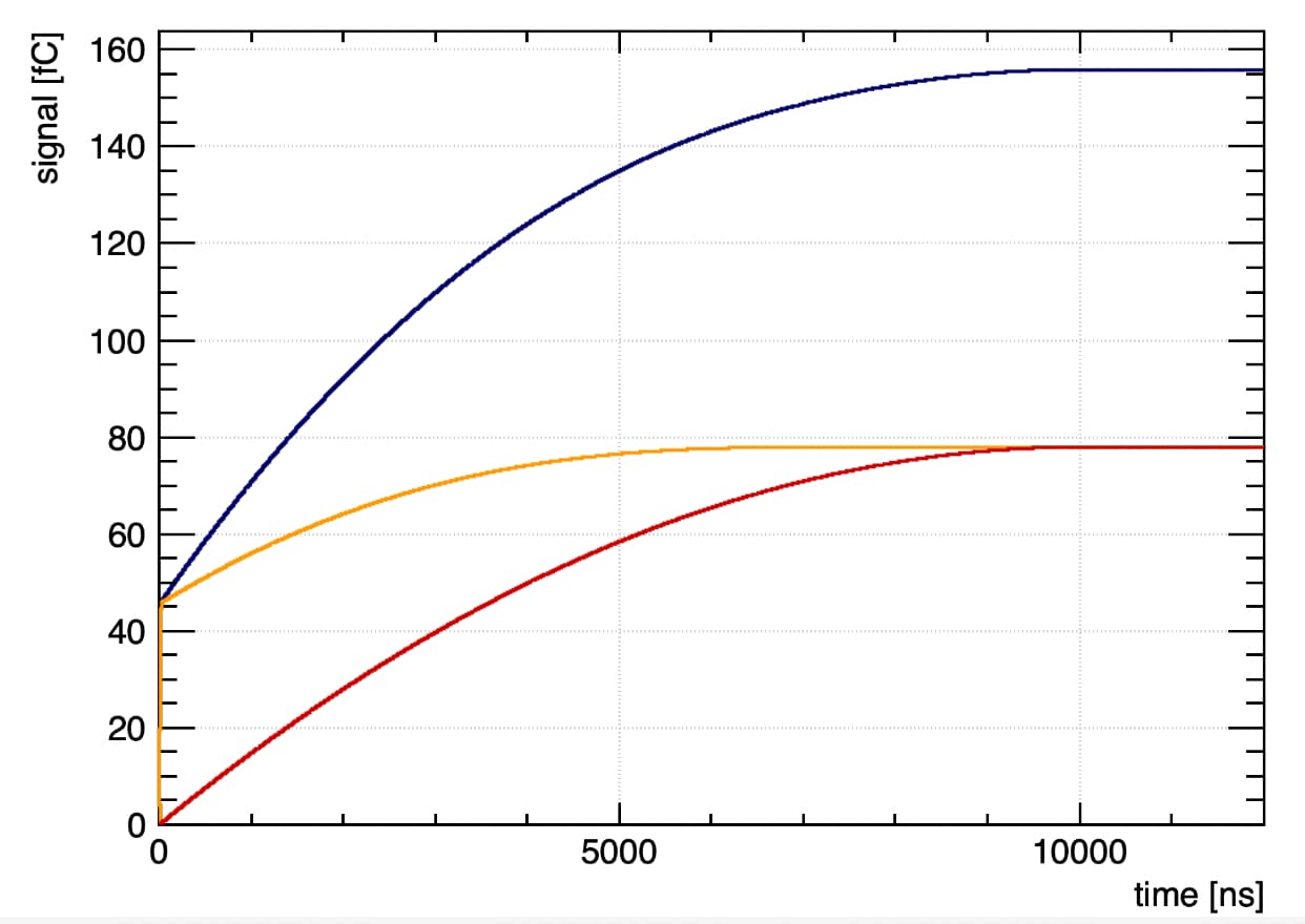
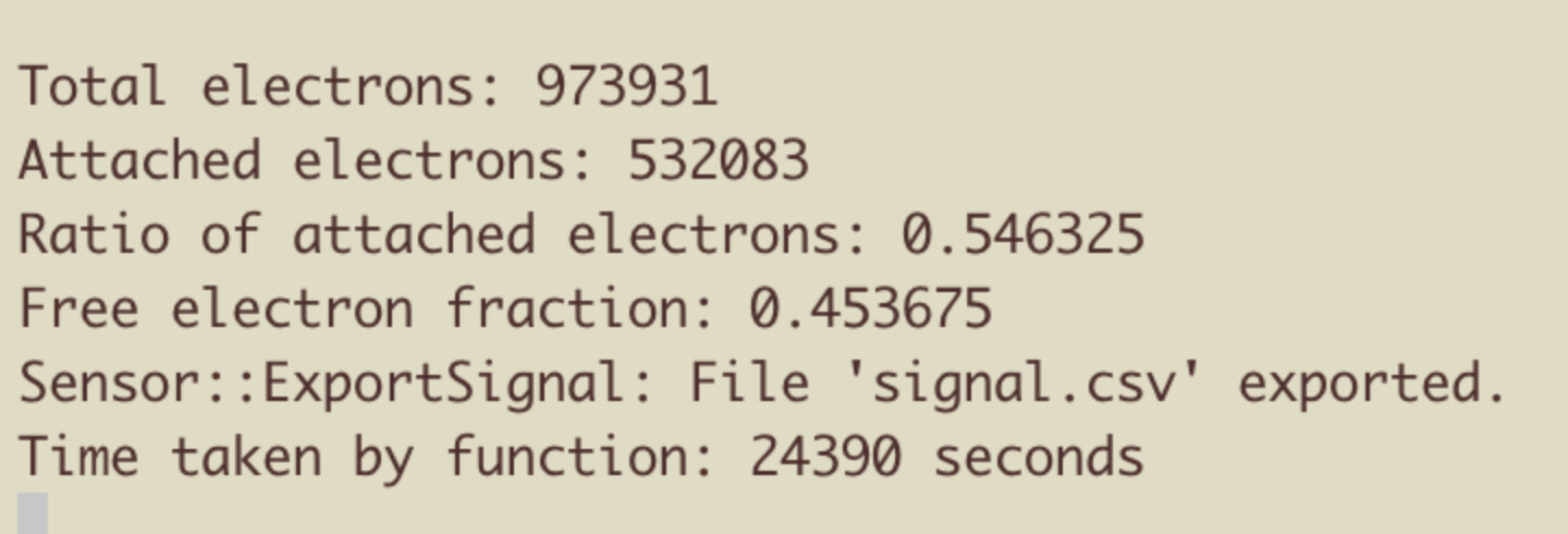
I managed to get the signal induced the electrons for a certain amount of tracks (100 in this case) but no signal is output by the positive or negative ions. On these 100 tracks the simulation couts 826 electrons and 425 attachment electrons so i expect 826 cations and 425 anions. Should’nt we see this amount of ions in the signal ?

I have checked all the forum in search of clues but nothing help me to make this work.
I load my ions mobilities:

gas.LoadIonMobility(path + "/share/Garfield/Data/IonMobility_N2+_N2.txt");
gas.LoadNegativeIonMobility(path + "/share/Garfield/Data/IonMobility_O2-_air.txt");

I use ViewSignal``, AvalancheMicroscopic for the electrons and ``DriftLineRKFfor the ions with drift.EnableIonTail() and drift.EnableSignalCalculation()

I managed to see a tiny signal by cheating putting an artificial drift.SetIonSignalScalingFactor(10) but this signal is completely flat during more than 1000 ns.

Is it normal in your opinion ? Thank you in advance, once again, for your answers.

Kind regards

Pierre G.

PS: I attached a piece of my code

  for (int i = 0; i < nEvents; ++i) {
    std::cout << "Event: " << i+1 << "/" << nEvents << "\n";
    // total number of electrons
    int nsum = 0;
    // number of attached electrons
    int asum = 0;
    // energy loss
    double esum = 0;
    // Initial position and direction 
    double x0 = 0., y0 = 0., z0 = 0., t0 = 0.;
    double dx0 = 1., dy0 = 0., dz0 = 0.; 
    sensor.NewSignal();
    track.NewTrack(x0, y0, z0, t0, dx0, dy0, dz0);

    for (const auto& cluster : track.GetClusters()) {
      esum += cluster.energy;
      for (const auto& electron : cluster.electrons) {
        aval.AvalancheElectron(electron.x, electron.y, electron.z, electron.t, 0.1, 0, 0, 0);
        // Loop over the electron avalanches.
        for (int j = 0; j < aval.GetNumberOfElectronEndpoints(); ++j){
          nsum ++;
          double xe1, ye1, ze1, te1, e1;
          double xe2, ye2, ze2, te2, e2;
          int status;
          aval.GetElectronEndpoint(j, xe1, ye1, ze1, te1, e1, xe2, ye2, ze2, te2, e2, status);
          drift.DriftIon(xe1, ye1, ye1, te1); 
          //drift.SetIonSignalScalingFactor(10);
          if (status == -7) {
            asum ++;
            drift.DriftNegativeIon(xe2, ye2, ye2, te2);
          }
        }
      }
    }
    vec_totalElectron.push_back(nsum);
    vec_attachedElectron.push_back(asum);
    vec_energyLoss.push_back(esum);
  }

Hi,

I think this is a message for @hschindl .

Cheers,
D

hi @pigerard nice to see your viewdrift :wink:

Well consider you have 1mm max distance for your ions to travel. I do not have the numbers, but I saw that in your previous post you wrote in your code that you have for ions in air. Assume here for order-of-magnitude estimate the Ar+ in Ar ion velocity of ~1.5cm2/V/s. Your electric field is 5kV/cm, then you expect a velocity (v = uE) of 7.5 mm/ms, so 1mm would be travelled in about 0.13ms. I would indeed expect the ion signal to last >> 1000 ns.

The signal is calculated by the Ramo-Schockley theorem: I = qvE, given that the charge and electric field are equal, but the velocity of the ions is about three orders of magnitude lower [*], you would expect an instantaneous current of about 1000 times lower. When you integrate the signal over the entire drift time of the species you will see that ions and electrons induce the same total charge Q.

[*] e- in argon: 55um/ns = 5.5cm/us for field of few kV/cm and with some CO2 in the mix
ion in argon: 0.75cm/ms (rather independent of field)
ratio ve/vi = 7.3E3

Hi @Piet thank you a lot for your answer.
For the driftview i did the maj and now I can have different color for the negative ions :slight_smile:

Effectively, when I have compared my result to other post in the forum i did’nt saw that sometimes the plots are integrated so the charge in function of the time and not the signal in function of the time. I still did’nt find the way to do it like that in Garfield so, in the meantime, I did it quickly in Python to verify. And yes The charges sums (nearly) to the same value ! ( why nearly ? 0.00534 fC for electrons+anions and 0.00519 for cations )

And i can estimated the fraction off attachment if I look closer to the electron charge (around 0.003 fC) in comparison with all the negative charges (around 0.0053 fC) !

Thank you again for all your answers, they’re a great help for me and the end of my master thesis.

Pierre G.

Hello @Piet , tiny update of my progress.
To get directly the integrated signal from Garfield it was just sensor.IntegrateSignals(); easy but I had to find it :slight_smile:. So now i have directly the charge per time from Garfield (same as my previous Python plots) but still the + and - charges do not sum exactly to the same value.

About the free electron fraction (FEF). I compared the value computed from the signal to the one got by checking the endpoint of the electrons.

a) By checking the endpoints i counted (on 1000 tracks of incident particles) n_e electrons and n_a attached electrons so a FEF of \left (1 - \frac{n_a}{n_e}\right ) = 0.450.

b) By checking the signal. The total charge ~ 1.6 fC match nearly exactly the number of electron n_e counted in the method (a) \left (n_e = \frac{1.6 \times 10^{-15}~\text{C}}{1.602 \times 10^{-19}~ \text{C}}\right ).
I interpret the free electrons as being the quick signal (so the signal up to ~ 0.45 fC). If i compute the FEF like \left (\frac{0.45~\text{fC}}{1.6~\text{fC}}\right ) = 0.281

I tough those two methods should give the same FEF ?

Hi,
sorry for the delay. If you release electron-ion pairs somewhere in your parallel-plate chamber and wait long enough until both the electrons and the positive ions have reached the electrodes to which they are drifting, then the induced charge will correspond to the number of charges collected at the electrode. Whether the induced charge is due to electrons or ions depends on the starting point of the electron-ion pair. If it’s in the middle of the gap, then the electron and ion contribute equally. If the electron-ion pair starts just above the positive electrode, then the signal will be completely dominated by the ion drift. If the starting points are uniformly distributed along the gap and there is no multiplication then I would indeed expect equal contributions from electrons and positive ions. Can you check if this is the case?
If you have a gain > 1, then the contributions are not equal any more (with increasing gain the ion one becomes more dominant).

hi @hschindl thank you for your time.

I do not compute the signal by putting electron-ion pair in the medium but by putting proton tracks so effectively the distribution of the pairs are not completely uniform in such a tiny sample.

I run a simulation for 10^5 tracks of protons hoping to have a more uniform ionization and it was the case. The negative charged and positive charge components are equal.

Again the total electrons produced match the number obtained by counting them but the free electron fraction is still far from the one obtained by doing the ratio of attached electrons.

On the signal plot the electronic charge is around 45fC. Hence the ratio \frac{~45 \text{fC}}{~160 \text{fC}}= 0.28 is quite far from 0.45.

Hi,
sorry for the late reply. Did you check (pen and paper, or with a toy simulation) that the two things are the same?

Hello, yes, I checked it and it is clearly not the same, it’s a bit more complicate. Thanks !