neBEM-based simulation is very slow

Hi, I’m trying so simulate a detector using Garfield++ on my Ubuntu install. The detector I am trying so simulate is an isobutane-filled MWPC, with two planes of wires (one going in x and one going in y directions) separated by a thin sheet of Mylar, which acts as a cathode. I used neBEM crossingWires.C as a basis for my work.

I think I have set up the geometry correctly (I am very new to Garfield, so that’s not a given), but the code takes a very long time to run. If I run the full setup using 12 cores, I have previously waited my entire 8-hour workday for results, and it was still processing. If I leave only a few wires and remove cathode, it runs pretty quick, but if I have either many wires or the Myalr cathode (or both), it slows down a lot.

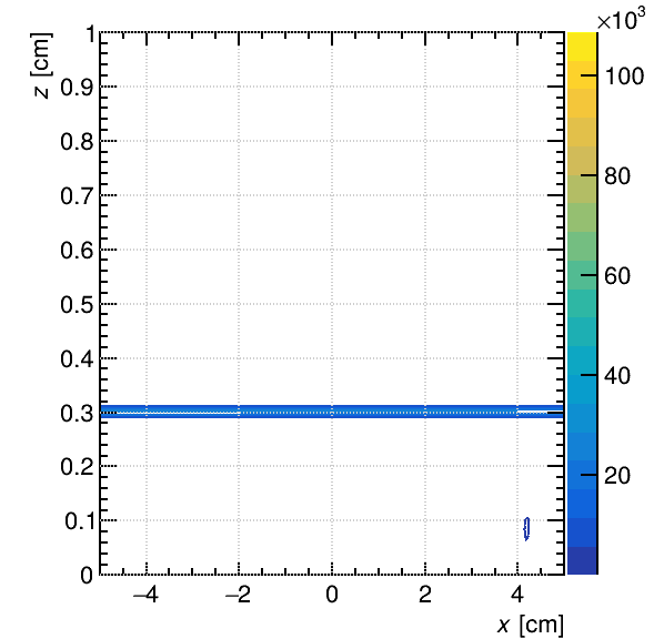
I can speed up the code by increasing the value in the function nebem.SetTargetElementSize(0.1), but I couldn’t find documentation which explains exactly what the function does, and reading source code was a bit confusing. If I increase the value, the fieldline plots I get are very strange though, they are mostly empty with only some occasional little bits of lines. If I reduce the number of wires though to 5 or less, I can see cocentric circles, as one would expect from an MWPC.

Below are my source code, and also a material file for Mylar, that I created. I also attach a plot for the field shape ion X-Z plane, which the code produces, and which I think looks completely incorrect (this was calculated by setting SetTargetElementSize() to 1).

crossingWires.C:

#include <iostream>
#include <cmath>
#include <vector>

#include <TApplication.h>

#include "Garfield/SolidWire.hh" 
#include "Garfield/SolidBox.hh" 
#include "Garfield/GeometrySimple.hh"
#include "Garfield/MediumMagboltz.hh"
#include "Garfield/MediumConductor.hh"
#include "Garfield/MediumMylar.hh"
#include "Garfield/ComponentNeBem3d.hh"
#include "Garfield/ViewField.hh"

using namespace Garfield;

int main(int argc, char* argv[]) {

  TApplication app("app", &argc, argv);

  MediumMagboltz gas("ic4h10", 100.);
  
  gas.SetPressure(5.250432); //7 mbar in torr
	gas.SetTemperature(293.15); //Kelvin
	gas.EnableThermalMotion(true);
	
  MediumConductor metal;

  // Geometry
  GeometrySimple geo;
  const double radius = 0.003;
  const double halflength = 5.; 
  
  std::vector< std::vector<SolidWire> > Wires;
  
  Wires.resize(2);
  
  float start_wire_pos = -4.8; //Position in cm of first wire in cm in along +/-5 cm axis
  float end_wire_pos = 4.8; //Same as above but last wire
  float pitch = 0.2; //Distance between wires in cm
  
  int N_wires = floor((end_wire_pos - start_wire_pos)) / pitch + 1; //Number of wires fitting into that space
  
  std::cout << std::endl << "Processing " << N_wires << " wires along x and y axis each." << std::endl << std::endl;
  
  for(int i = 0; i < N_wires; i++){
  	
  	float wire_pos = start_wire_pos + (float)i * pitch;
  	
		SolidWire wire1(0., wire_pos, 0.3, radius, 2. * halflength, 1, 0, 0);
		SolidWire wire2(wire_pos, 0., 0.9, radius, 2. * halflength, 0, 1, 0);
		
		wire1.SetBoundaryPotential(+650.);
		wire2.SetBoundaryPotential(+650.);
		
		Wires[0].push_back(wire1);
		Wires[1].push_back(wire2);
  }
  
  for(int i = 0; i < (int)Wires[0].size(); i++){
		
		geo.AddSolid(&Wires[0][i], &metal);
		geo.AddSolid(&Wires[1][i], &metal);
  }
  
  MediumMylar mylar;
  
  SolidBox cathode(-5., -5., 0.6, 10., 10., 0.00009);
  
  cathode.SetBoundaryPotential(0.);
  
  geo.SetMedium(&gas);
  
  geo.AddSolid(&cathode, &mylar);
	
  ComponentNeBem3d nebem;
  nebem.SetGeometry(&geo);
  nebem.SetTargetElementSize(1);
  nebem.UseSVDInversion();
  nebem.SetNumberOfThreads(12);
  nebem.Initialise();
 
  ViewField fieldView1(&nebem);
  ViewField fieldView2(&nebem);
  ViewField fieldView3(&nebem);
  
  fieldView1.SetArea(-5., -5., 0., 5., 5., 1.);
  fieldView2.SetArea(-5., -5., 0., 5., 5., 1.);
  fieldView3.SetArea(-5., -5., 0., 5., 5., 1.);
  
  fieldView1.SetPlaneXY();
  fieldView1.PlotContour("e");
  
  fieldView2.SetPlaneXZ();
  fieldView2.PlotContour("e");
  
  fieldView3.SetPlaneYZ();
  fieldView3.PlotContour("e");
	
	gas.WriteGasFile("isobutane.gas");
	
  app.Run(true);
}


MediumMylar.hh:

#ifndef G_MEDIUM_MYLAR_H
#define G_MEDIUM_MYLAR_H

#include "Medium.hh"

namespace Garfield {

class MediumMylar : public Medium {
 public:
  /// Constructor
  MediumMylar();
  /// Destructor
  virtual ~MediumMylar() {}

  bool IsSemiconductor() const override { return false; }

 private:
  // Band gap energy [eV]
  // m_bandGap = ;
  // Low-field mobility = ;
};
}
#endif

MediumMylar.cc:

#include <iostream>

#include "Garfield/MediumMylar.hh"
#include "Garfield/GarfieldConstants.hh"

namespace Garfield {

MediumMylar::MediumMylar() : Medium() {
  m_className = "MediumMylar";
  m_name = "Mylar";

  SetTemperature(293.15);
  SetDielectricConstant(3.2);
  Medium::SetAtomicNumber(6.456261);
  Medium::SetAtomicWeight(12.877382343);
  Medium::SetMassDensity(1.39);

  m_driftable = false;
  m_ionisable = true;
  m_microscopic = false;

  m_w = 78.7; //Mean ionization energy: https://advlabs.aapt.org/bfyiii/files/BFYIIIWorkshop20AlphaParticleSpectroscopyandEnergyLoss.pdf
}

}
Hello @Nsos,

@hschindl might be able to help you!

Cheers,
Devajith

1 Like

Hi,
apologies for the late reply! I’m looping in @pratikm who is the main author of neBEM and may be able to advise.
neBEM can indeed be a bit slow if there are many boundary elements.

  • Can you try to reduce the number of wires? Since you have a periodic structure, could you try to model only the “elementary” cell and then set the number of periodic copies to be simulated?
  • Try to make the cathode infinitely thin, i. e.
SolidBox cathode(-5., -5., 0.6, 10., 10., 0.);

such that only the cathode plane is modelled (instead of a box).

Also, but this is just a detail, you don’t need to create a MediumMylar, you can just use MediumConductor; for the purpose of the field calculation, the only thing that matters is the potential you apply to the cathode.

1 Like

Hi @hschindl! Thank you for the feedback and the info. I guess my post was really several questions wrapped into one, so my apologies for that.

Reducing the number of wires is entirely plausible, although for that, my question is: what does SetTargetElementSize() function do? I didn’t really understand the source code for it. If it changes the “step” size in calculations, is there a possibility that I make it too wide and average over many wires? I would probably need to calibrate this parameter, particularly if I am reducing the number of wires I simulate. This may perhaps be more of a question for @pratikm

Infinitely thin cathode is fine within the confines of my present simulation, although I was planning later of injecting energetic electrons into it and measuring avalanche multiplication in the MWPCs. The primary electrons will need to punch through the Mylar cathode (it’s my understanding that SRIM or maybe SREM would be used for that, right?). In such a case, my cathode would need to have a thickness.

Hi NSos,
Please allow me a day. I’ll try to answer at least some of your questions tomorrow. I’ll also try to execute the code that you sent earlier.
Best,
Supratik

1 Like

Hi Supratik! Thank you very much for having a look, and no problem at all! Didn’t mean to rush you.

Hi NSos,

SetTargetElementSize passes the preferred element size to neBEM. This may be honoured by the solver if the resulting number of elements is within the acceptable range of number of elements (decided by the MinNbElements and MaxNbElements).
These are the numbers that we pass to neBEM to decide the spatial discretization on line (wire), or area (rectangle, triangle) primitives that constitute a device.
I hope this helps.
Next, I’ll try to execute your code and try to understand the problems that you are facing.

Best,
Supratik

1 Like

Please use LU inversion, rather than SVD. SVD is known to be very slow and does not have OpenMP implemented on it.

1 Like

Hi Supratik, thank you for checking everything. I think this reply is a bit higher level than my current understanding. I understand what you mean about discretization of the wire, but what units then is the input to neBEM? Is it in cm/mm, or some fraction of the length?

Hi,
in the function SetTargetElementSize of ComponentNeBem3d, the unit is cm.

1 Like

Great, thank you for clarifying. The last part of my question was concerning the resulting plots. Every time I run the code, the final plots from functions like SetPlaneXY() end up looking different. I am not sure how the plane where z-axis is cut is chosen. Is there a way to fix this parameter, so that the plots are reproducible?

That’s true. On the other hand, for the SRIM simulation I guess you don’t care about the electric field in the wire chamber, so I think you can factorise these two stages of your simulation…

1 Like

Hmm, that is strange. SetPlaneXY should set up an xy projection at z = 0. If you get different results from run to run then something is not quite right. Is it the geometry plot that is not reproducible or “only” the electric field one?

1 Like

Regarding your first reply, I was hoping to calculate the avalanche multiplication ratio produced in this MWPC by an electron with enough energy that it passes through the cathode plane. For this, I need both the electric field and also SRIM components of Garfield.

Regarding the plotting, I attach a set of plots from 3 consecutive executions of my code (thanks to @pratikm for suggesting LU for speed!). The plots show YZ plane, and they are all different. Further to your reply, is there a way to write out the electric field as some sort of a matrix in text form? And you mention geometry plots, but I don’t think my code features any, and I would like to have a look. How do you do that?

Sorry for such a multitude of questions, I am very new to Garfield, and thanks again for all the help!

This topic was automatically closed 14 days after the last reply. New replies are no longer allowed.