Is it possible to simulate a grid ionization chamber

Hello

I built an ionization chamber containing two plates and a grid. The ionization chamber is divided into a drift zone and an induction zone. I thought that the grid could shield the signals of ions and electrons in the drift zone.

However, the final result is basically consistent with the ionization chamber signal without the grid, and the shielding effect of the grid is not reflected.

Maybe there’s a problem with my model? Or is it that garfeild++ cannot simulate the effect of electrostatic shielding.

thanks

Can you provide a bit more details about your model? What method did you use for computing the weighting potential or weighting field?

hello This is my code

int main(int argc, char * argv[]) {

  TApplication app("app", &argc, argv);


  // Periodicity (wire spacing) [cm].

  constexpr double period = 0.1;

  // Wire diameters [cm]直径

  // Gate wires.

  constexpr double dg = 0.01;

  // Voltage settings [V].

  // Gate wires.

  constexpr double vg = -460.;


  // HV plane (drift field).

  constexpr double yHV = 0.2;

  constexpr double vHV = -5;


  // Setup the gas.

  MediumMagboltz gas;

  // Set the temperature [K] and pressure [Torr].

  gas.SetComposition("xe", 100.); //100%Xe

  gas.SetTemperature(293.15);

  gas.SetPressure(15*760.);

  gas.Initialise(true);  

  // Load the ion mobilities.

  const std::string path = std::getenv("GARFIELD_HOME");

  gas.LoadIonMobility(path + "/Data/IonMobility_Xe+_P12_Xe.txt");

  // Setup the electric field.

  ComponentAnalyticField cmp;

  cmp.SetMedium(&gas);

  cmp.SetPeriodicityX(period);

  // Add the gate wires.

  constexpr double xg1 = 0.5 * period;

  constexpr double xg2 = 0.75 * period;

  constexpr double yg = 0.075;


  cmp.AddWire(xg1, yg, dg, vg , "g+", 100., 50., 19.3, 1);

  //cmp.AddWire(xg2, yg, dg, vg , "g-", 100., 50., 19.3, 1);


  // Add the planes.

  cmp.AddPlaneY(0., -1000., "pad_plane");

  cmp.AddPlaneY(yHV, vHV, "HV");

  // Request weighting-field calculation for the pad plane.

  cmp.AddReadout("pad_plane");


  // Make a sensor.

  Sensor sensor;

  sensor.AddComponent(&cmp);

  sensor.AddElectrode(&cmp, "pad_plane");

  // Change the time window for less/better resolution in time

  // (effect on convolution can be important).

  const double tstep = 1000;      //信号采样步长,0.1微秒 (ns,s=1e9ns)

  const double tmin = 0;         //信号采样时间下限

  const double tmax=3000000;     //上限,根据结果调整  暂定1ms  

  const unsigned int nbins = (tmax-tmin)/tstep;   //信号采样时间间隔数 ,随机取样

  sensor.SetTimeWindow(tmin, tstep, nbins);

  constexpr double xmin = -3 * period;

  constexpr double xmax =  3 * period;

  sensor.SetArea(xmin, 0., -1., xmax, yHV, 1.);

  // Plot isopotential contours.

  ViewField fieldView;

  fieldView.SetSensor(&sensor);

  fieldView.SetArea(xmin, 0., xmax, 0.2);

  fieldView.SetVoltageRange(0., 1000.);

  fieldView.PlotContour();

  // Calculate ion drift lines using the RKF method.

  DriftLineRKF driftline;

  driftline.SetSensor(&sensor);

  // Plot the drift line.

  ViewDrift driftView;

  // Comment this out when calculating many drift lines.

  driftline.EnablePlotting(&driftView);


  // const int nIons = 10000;

  const int nIons = 10000;

  // Count the number of ions that drift to

  // plane, cathode, gate or drift volume, respectively.

  for (int i = 0; i < nIons; i++) {

    // Sample the starting point of the ion around the sense wire.

    const double x0 = 0.4* RndmUniformPos()-0.2;//25mm

    const double y0 = 0.07* RndmUniformPos();

    driftline.DriftIon(x0, y0, 0, 0);

  }

  // Plot the drift lines on top of the cell layout.

  ViewCell cellView;

  cellView.SetComponent(&cmp);

  cellView.SetArea(xmin, 0., xmax, 0.2);

  cellView.Plot2d();

  driftView.SetArea(xmin, 0., xmax, 0.2);

  driftView.SetCanvas(cellView.GetCanvas());

  driftView.Plot(true, false);

  // Plot the induced current.

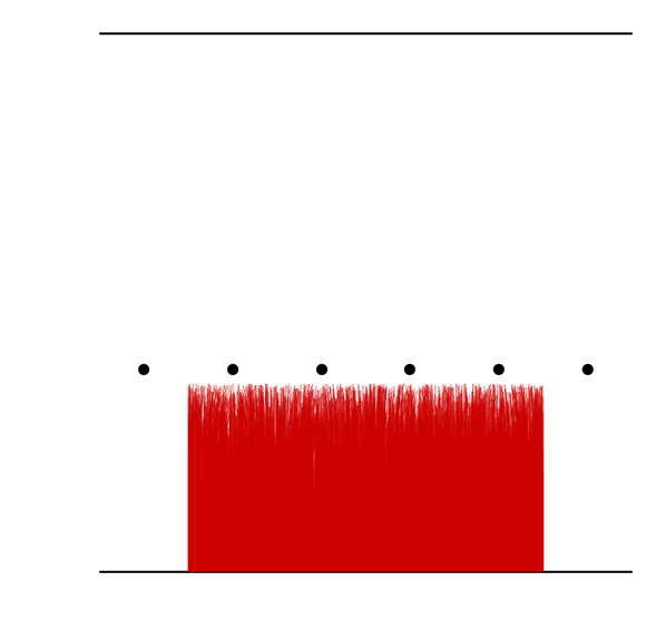
  ViewSignal signalView;

  signalView.SetSensor(&sensor);

  TCanvas c1("c1", "", 800, 600);

  signalView.SetCanvas(&c1);

  signalView.PlotSignal("pad_plane");

  // Convolute with the transfer function and plot again.

  sensor.SetTransferFunction(transfer);

  constexpr bool fft = true;

  sensor.ConvoluteSignals(fft);

  TCanvas c2("c2", "", 800, 600);

  signalView.SetCanvas(&c2);

  signalView.SetLabelY("signal [mV]");

  signalView.PlotSignal("pad_plane");

  app.Run(true);

}

Hello ,I use ComplexAnalyticField to calculate the weight field. The specific code is given below.

Hi,
thanks for the code! You have cathode plane at y = 0, an array of wires at y = 0.075 cm and an anode plane at y = 0.2 cm. In your program, the ion drift lines start somewhere between y = 0 and y = 0.07 so they all drift to the plane at y = 0 which is also your readout plane. In what sense would you expect this signal to be shielded by the wires?

I’m sorry to confuse you. I didn’t make it clear.Please ignore the drift line of ions. I upload this picture just to illustrate the distribution of electrodes in the detector.

I found that the voltage of the electrode in my code was wrong. The electrode should be connected with positive voltage, which should be 5V, 460V and 1000V.

I want to randomly generate ions in the range of y = 0 ~ 0.2cm, and then shield ions in the range of y = 0.075 ~ 0.2cm. Theoretically, the output signal is only related to ions in the range of y = 0 ~ 0.075cm.

Below, I give a correct code about voltage again.

Thanks

/ Periodicity (wire spacing) [cm].

  constexpr double period = 0.1;
  // Wire diameters [cm]直径
  // Gate wires.
  constexpr double dg = 0.01;

  // Voltage settings [V].
  // Gate wires.
  constexpr double vg = 460.;
 
  // HV plane (drift field).
  constexpr double yHV = 0.2;
  constexpr double vHV = 5;


  // Setup the gas.
  MediumMagboltz gas;

  // Set the temperature [K] and pressure [Torr].
  gas.SetComposition("xe", 100.); //100%Xe
  gas.SetTemperature(293.15);
  gas.SetPressure(15*760.);
  gas.Initialise(true);  

  // Load the ion mobilities.
  const std::string path = std::getenv("GARFIELD_HOME");
  gas.LoadIonMobility(path + "/Data/IonMobility_Xe+_P12_Xe.txt");

  // Setup the electric field.
  ComponentAnalyticField cmp;
  cmp.SetMedium(&gas);
  cmp.SetPeriodicityX(period);

  // Add the gate wires.
  constexpr double xg1 = 0.5 * period;
  constexpr double xg2 = 0.75 * period;
  constexpr double yg = 0.075;
  cmp.AddWire(xg1, yg, dg, vg , "g+", 100., 50., 19.3, 1);
  //cmp.AddWire(xg2, yg, dg, vg , "g-", 100., 50., 19.3, 1);

  // Add the planes.
  cmp.AddPlaneY(0., 1000., "pad_plane");
  cmp.AddPlaneY(yHV, vHV, "HV");

  // Request weighting-field calculation for the pad plane.
  cmp.AddReadout("pad_plane");

Hi,
thanks for the clarification! You’re right, there is an issue with the calculation of the weighting field for this configuration. I’m looking into it… As a work-around you can add additional copies of the wire, something like this:

ComponentAnalyticField cmp;
cmp.SetMedium(&gas);
cmp.SetPeriodicityX(9 * period);
// Add the gate wires.
constexpr double yg = 0.075;
cmp.AddWire(-4 * period, yg, dg, vg, "g+");
cmp.AddWire(-3 * period, yg, dg, vg, "g+");
cmp.AddWire(-2 * period, yg, dg, vg, "g+");
cmp.AddWire(-1 * period, yg, dg, vg, "g+");
cmp.AddWire(0, yg, dg, vg, "g+");
cmp.AddWire(+1 * period, yg, dg, vg, "g+");
cmp.AddWire(+2 * period, yg, dg, vg, "g+");
cmp.AddWire(+3 * period, yg, dg, vg, "g+");
cmp.AddWire(+4 * period, yg, dg, vg, "g+"); 

Thanks for your help, I will modify my code as you suggest.

Hi,
just to follow up on this. I committed some changes that should help fix this problem (Weighting fields/potential in periodic geometries (!300) · Merge requests · garfield / garfieldpp).
ComponentAnalyticField now has a function SetNumberOfCellCopies that you can use to control the way weighting potentials/fields are calculated. In your case, the best solution would be to add a line

cmp. SetNumberOfCellCopies(0);

Then you can keep the original cell layout (only one wire) with the original periodicity.

ok,Thank you very much.

This topic was automatically closed 14 days after the last reply. New replies are no longer allowed.