Dear all,
I want to simulate induced signal for SeF5- fly in SeF6. Following the suggestion, I use SF6 instead. My first question is that is it necessary to build gas file using Magboltz if the gas had been defined? I tried to generate gas file about SF6, but it mentioned me “PROGRAM STOPPED TOO MANY PRIMARIES IPRIM”. Although I enhanced the range of electric field.
And the model was built by COMSOL, with also the weight potential.
Of course it seems abnormal. So my second question is what’s wrong to my code?
Another question is that the ion is negative ion, so when using drift.DriftNegativeIon(0,0,9.5,0), the induced charge is 0. Why such thing happens?
Thanks Induced.C (3.1 KB) Potential.txt (291.0 KB) SeF5-_SeF6.txt (309 Bytes) WeightPotential.txt (293.1 KB)
Hi,
at what electric field did you get the “PROGRAM STOPPED…” error message from Magboltz? In pure SF6, electron attachment happens very quickly and you might be running the simulation at conditions where you don’t get meaningful macroscopic transport parameters (drift velocity etc.).
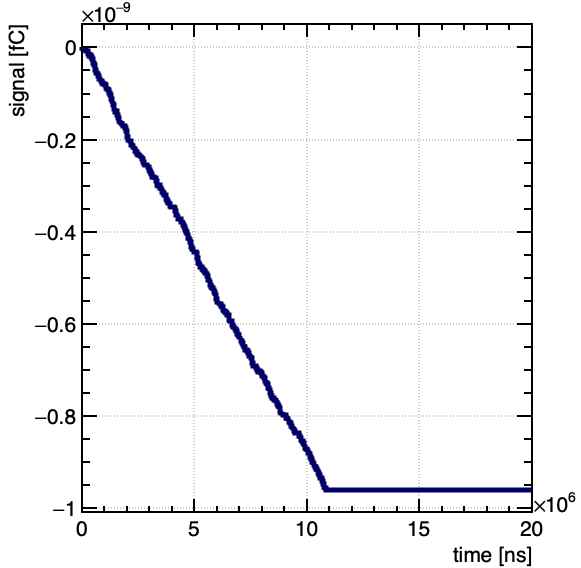
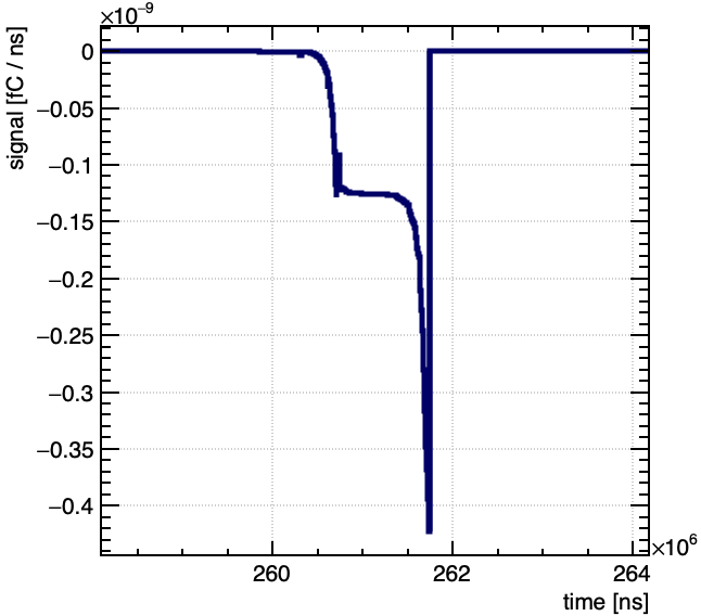
The plot you attached seems to be the induced charge as function of time (as opposed to the induced current). Can you explain in more detail why it looks abnormal?
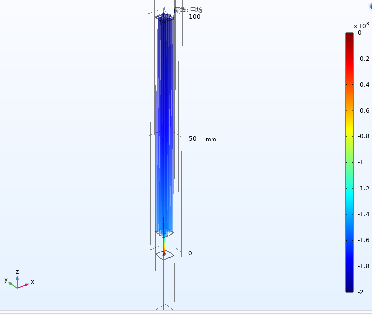
Regarding the negative ion drift: where is the starting point (0, 0, 9.5) with respect to the readout electrode? Can you make a plot of the drift line?
It is consisted by cathode (top), focus plane (a hole in the middle of plane) and anode (hexagon area). The voltage of cathode is -2000 V and the voltage of focusing plane is -1500 V.
Starting point (0, 0, 9.5) means the ion should be at the center and z = 95 mm.
What I expected is that the induced charge should back to 0 as the increasing drift time. Besides, the drift velocity of ions is too slow, the time should be longer.
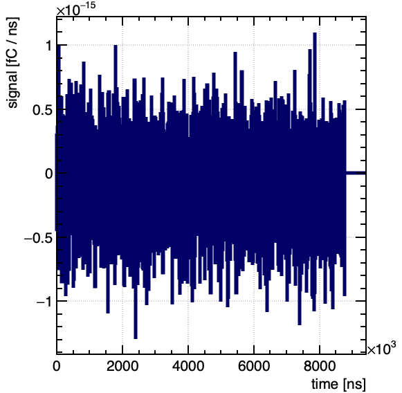
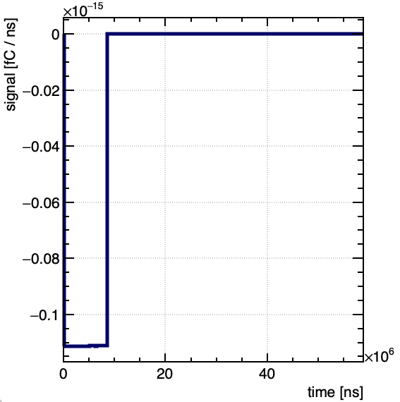
Here is the result of induced current vs time. Looks like white noise.
Dear @dm-leo can you provide also your field files (mesh_induced.mphtxt, dielectric.dat, Potential.txt) such that we can run your example code?
Thanks
Piet
What is the electric field at the starting point of your ion? Assuming the region between the cathode and the focusing plane can be approximate by a parallel plate chamber, I guess the field will be around 500 V / 10 cm = 50 V / cm, which is quite low.
What is the drift velocity that you expect at that field given the mobility value you are using? And what would be the drift time of the ion?
Hi, of course the electric field is quite low. The reduced mobility I calculated is about 0.444, so the velocity is about 2 cm/s. The time should be larger than 5 s. So at least us is not suitable.
Hi,
on the last plot you’ve posted (the one showing the induced current as function of time), the duration of the signal is ~9 ms, and it’s for the positive ion (so over a distance of 5 mm), so the order of magnitude doesn’t seem completely wrong. But I agree that the current looks a bit small. Can you try to switch off diffusion (function DisableDiffusion in AvalancheMC)? You might also want to increase the step size (1 μm seems a bit small for the scale of the device you are simulating).
Ah, I see what you mean. GetIonSignal returns the signal induced by positive charge carriers, GetElectronSignal returns the signal induced by negative charge carriers, i. e. electrons and negative ions.