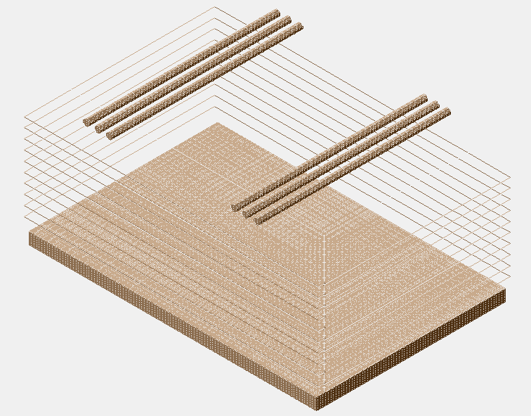
I am trying to simulate something that is somewhat similar to the given DriftTube example. What I want to do is to have a cathode plate on the bottom, some anode wires (3) above the plate, and in the drift region between the anode wires and the cathode plate, there will be rectangular loops of wires that encompasses the whole drift region (picture is attached). Adding the anode wires is easy, I can just use the AddWire function, but for the loops of wire and the cathode plate, I am having some trouble with. I would like some help on how to do this or at least where I can look up information on how to do this.
I am still reading the user guide, so if there is specific region that I need to focus on, please let me know. Also, the loops of wire does not necessarily be one continuous piece of wire. Instead it can be four segments adding up to make a rectangle. Thank you in advance.
I guess that @hschindl can help you.
Hello,
apologies for my late reply. The semi-analytic methods implemented in ComponentAnalyticField (the class used in the DriftTube example) can be used for calculating the electric field for two-dimensional layouts. You can find some examples in
Adding the cathode plane is straightforward, the corresponding functions are called AddPlaneX (if you want a horizontal plane as in your case) and AddPlaneY (if you want a vertical plane).
Simulating the rectangular wires surrounding the chamber is not possible with this class however. If you limit yourself to the central region of the chamber, far away from the edge, maybe you can omit these wires?
If you do need the rectangular wires for your simulation, you could use an external finite-element field solver such as Ansys or Elmer to calculate the field and import the resulting field map into Garfield. This might also be a bit tricky though since your field map might become very large since you’ll need fine binning close to the wires and you can’t exploit periodicity/symmetries to limit the size of the mesh.
A third possibility (which could be well suited for you problem) would be to use the “neBEM” field solver. We are in the process of finalizing the validation of the interface to this solver, should be ready in a couple of weeks’ time.
Thank you, @hschindl. I have another question. Is there a way to add in a grid of wire? Something like a Frisch grid.
In ComponentAnalyticField you can enter a grid/row of wires using the function AddWire. If you need to model a grid with crossing wires, you would have to use a FEM solver (or, in the very near future, neBEM).