I want to get the weight.lis to set weight field by componentansys123 class, and finally get the current signal, but the example notice that we should set the potential volume1 to 1V, and potential of other volumes to 0V, the potentials on top of the gas and substrate are set to 0V as well.
Now the problem is my model only has gas area and the metal part has been deleted for simplify.
So what should I do to get the weight.lis files
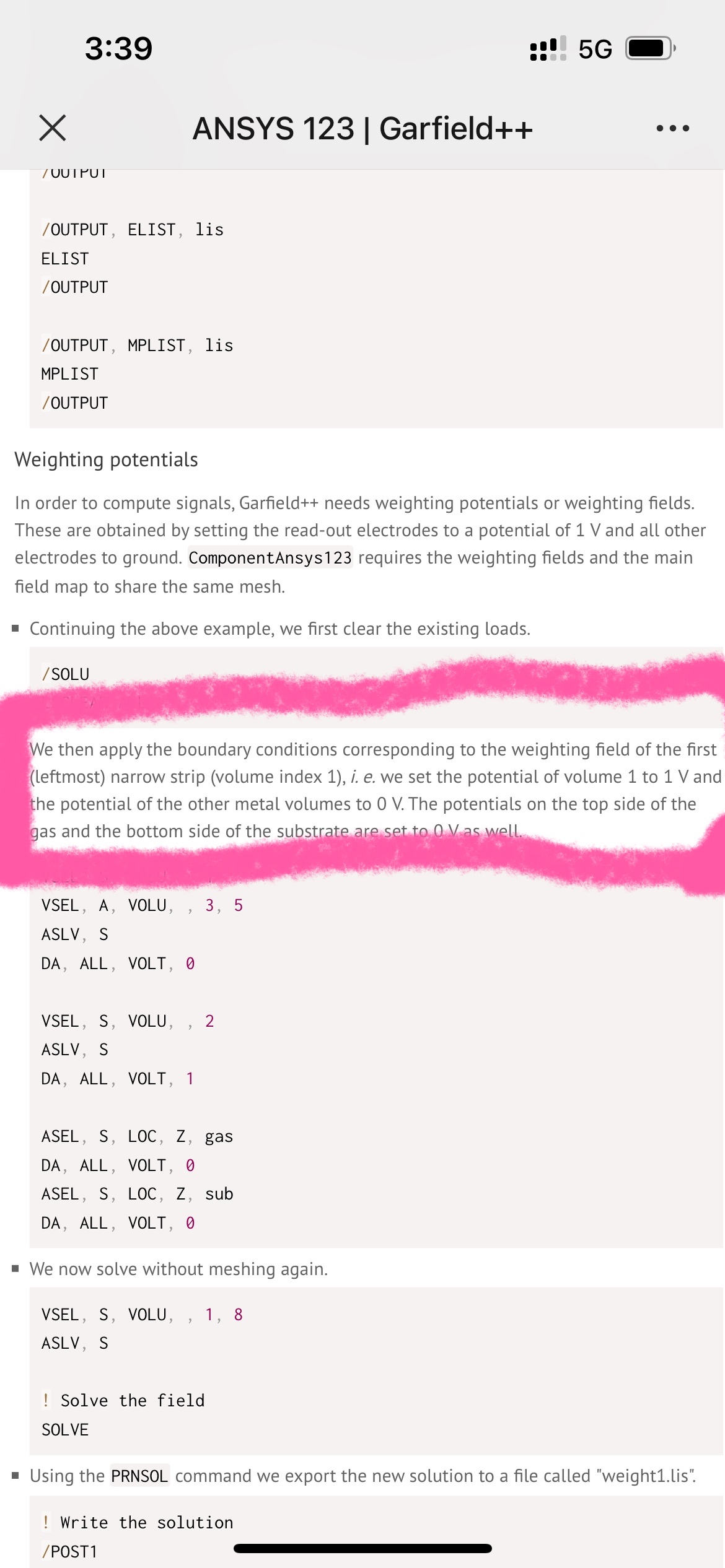
It’s not necessarily a problem if there are no metal volumes in your field map. I assume you have applied fixed-voltage boundary conditions to some of the surfaces in your geometry when solving for the “drift” electric field/potential. Instead of using the “real” potentials, apply 1 V to the area that corresponds to the readout electrode and 0V to the others to get the weighting field/potential.
Hi,
Thanks a lot for your help
your advice is really helpful and I will try to get the correct results.
Hi,
I have got my induced current, however it is a little bit weird. The result is like this below
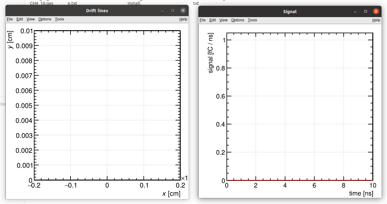
And my code is this:
#include <iostream>

#include <TApplication.h>
#include <TH1F.h>
#include <TCanvas.h>

#include "Garfield/MediumSilicon.hh"
#include "Garfield/ComponentConstant.hh"
#include "Garfield/Sensor.hh"
#include "Garfield/TrackTrim.hh"
#include "Garfield/DriftLineRKF.hh"
#include "Garfield/ViewDrift.hh"
#include "Garfield/ViewSignal.hh"
#include "Garfield/ComponentAnsys123.hh"
#include "Garfield/MediumMagboltz.hh"

using namespace Garfield;

int main(int argc, char *argv[]) {

  // Application
  TApplication app("app", &argc, argv);

  ComponentAnsys123 fm;
  fm.Initialise("ELIST.lis", "NLIST.lis", "MPLIST.lis", "PRNSOL.lis", "cm");
  fm.SetWeightingField("weight1.lis", "readout");
  double x0, y0, z0, x1, y1, z1;
  fm.GetBoundingBox(x0, y0, z0, x1, y1, z1);


  // Define the medium.
  MediumMagboltz gas;
  gas.LoadGasFile("Ar_90_CH4_10.gas");
  fm.SetMedium(0, &gas);

  Sensor sensor;
  sensor.AddComponent(&fm);
  sensor.AddElectrode(&fm, "readout");
  // Set the time bins for the induced current.
  const unsigned int nTimeBins = 1000;
  const double tmin =  0.;
  const double tmax = 10.;
  const double tstep = (tmax - tmin) / nTimeBins;
  sensor.SetTimeWindow(tmin, tstep, nTimeBins);

  // Read the TRIM output file.
  TrackTrim tr;
  const std::string filename = "EXYZ-P10.txt";
  // Import the first 100 ions.
  if (!tr.ReadFile(filename, 100)) {
    std::cerr << "Reading TRIM EXYZ file failed.\n";
    return 1;
  }
  tr.SetWorkFunction(26);
  tr.SetFanoFactor(0.179);
  // Connect the track to a sensor.
  tr.SetSensor(&sensor);

  DriftLineRKF drift;
  drift.SetSensor(&sensor);
  drift.SetMaximumStepSize(10.e-4);

  // Plot the track and the drift lines.
  ViewDrift driftView;
  tr.EnablePlotting(&driftView);
  drift.EnablePlotting(&driftView);

  // Simulate an ion track.
  tr.NewTrack(-0.1, 0.204, -0.07, 0., 0., -1., 0.);
  // Loop over the clusters.
  double xc, yc, zc, tc, ec, ekin;
  int ne = 0;
  while (tr.GetCluster(xc, yc, zc, tc, ne, ec, ekin)) {
    // Simulate electron and ion drift lines starting
    // from the cluster position.
    // Scale the induced current by the number of electron/ion pairs
    // in the cluster.
    drift.SetElectronSignalScalingFactor(ne);
    drift.DriftElectron(xc, yc, zc, tc);
    drift.SetHoleSignalScalingFactor(ne);
    drift.DriftHole(xc, yc, zc, tc);
  }
  driftView.SetArea(-2.e-4, 0., 2.e-4, 100.e-4);
  driftView.Plot(true);

  ViewSignal signalView;
  signalView.SetSensor(&sensor);
  signalView.PlotSignal("readout", true, true, true);

  app.Run();
  return 0;
}
would you please help me to see about this?
See