hello
I used AvalancheMC() to simulate an electron amplifying in an avalanche region and get its sensed signal at a specific electrode. I found that when I did not simulate the drift line of the avalanche electron ion (that is, remove mc.DriftIon() and mc.DriftElectron()), the induced signal was much smaller than when drawing the track (this should not caused by falling); therefore, can these two lines of code be deleted when simulating induction signals? ; So, can you tell me the calculation principle of the induced signal in the simulation? Also, I’m wondering why when I add these two lines of code, mc.DriftIon() (line 353) and mc.DriftElectron() (line 351), it runs so slow? Shouldn’t this be a huge amount of calculation?
signal.txt (12.5 KB)
@hschindl can most probably help you
Hi,
The induced current is calculated using the Shockley-Ramo theorem.
I’m not sure I understand your program btw. It first simulates an electron avalanche using microscopic tracking (AvalancheMicroscopic), then loops over the electron trajectories in the avalanche and simulates electron and ion drift lines from the starting point of each electron.
This effectively simulates every electron twice, which I don’t think is what you want.
I don’t understand why it’s being calculated twice, is it because I’m using both AvalancheMicroscopic() and AvalancheMC() methods?
Yes, ish.
aval.AvalancheElectron(x0, y0, z0, t0, e0, 0., 0., 0.);
// Loop over the electron trajectories in the avalanche.
const unsigned int np = aval.GetNumberOfElectronEndpoints();
for (unsigned int j = 0; j < np; ++j) {
  double xe1 = 0., ye1 = 0., ze1 = 0., te1 = 0., e1 = 0.;
  double xe2 = 0., ye2 = 0., ze2 = 0., te2 = 0., e2 = 0.;
  int status = 0;
  // Get the start and end point of the electron.
  aval.GetElectronEndpoint(j, xe1, ye1, ze1, te1, e1, xe2, ye2, ze2, te2, e2, status);
  // Simulate an ion drift line starting from the point where the electron was created.
  mc.DriftIon(xe1, ye1, ze1, te1);
  // This is the line that doesn't make sense. You already simulated this electron.
  mc.DriftElectron(xe1, ye1, ze1, te1);
}
Thank you very much! I think I’m confusing avalanche electrons and drift electrons; you mean I don’t need to use mc.DriftElectron() to simulate the drift of avalanche electrons? aval.AvalancheElectron() has simulated the entire process of electron avalanche and the subsequent drift of electrons?
Yes, that’s correct.
I’m so sorry, but please take a look at my code! Why does it always get stuck when I run it; is this caused by using AvalancheMC()? Is DriftRKF() a better choice?
GridIonization.zip (245.6 KB)
If you have a large number of primary electron-ion pairs (which I assume is the case in your application since you simulate an α particle) then DriftRKF is probably indeed a better choice. Maybe have a look at this example: Examples/Srim/trimsignal.C · master · garfield / garfieldpp · GitLab
It uses TRIM instead of SRIM but otherwise it’s quite similar.
Btw, I don’t quite understand the logic of the program. Why do you first simulate an electron drift line (without multiplication) using DriftElectron and then call AvalancheElectron?
track.NewTrack(x0, y0, 0, 0, -1, -1, 0);
double xc = 0., yc = 0., zc = 0., tc = 0., ec = 0., extra = 0.;
 int nc = 0;
 while (track.GetCluster(xc, yc, zc, tc, nc, ec, extra)) {
  for (int k = 0; k < nc; ++k) {
    mc.DriftIon(xc, yc, zc, tc);
    mc.DriftElectron(xc, yc, zc, tc);
    double xe1 = 0., ye1 = 0., ze1 = 0., te1 = 0.;
    double xe2 = 0., ye2 = 0., ze2 = 0., te2 = 0.;
    int status = 0;
    mc.GetElectronEndpoint(0,xe1, ye1, ze1, te1, xe2, ye2, ze2, te2, status);
    if (ye2 > ya + 0.01) continue;
    // Why?
    mc.AvalancheElectron(xe2, ye2, ze2, te2);
}
It is like this, first the drift of the primordial electrons, and then the avalanche amplification of the electrons that have drifted into the amplified region. The logic should be fine, right?
How do you define the amplification region? DriftElectron will normally drift the electron until it hits the wire (or another electrode). I don’t see why you wouldn’t use AvalancheElectron in the first place; as long as the field is too low for multiplication to happen, it will do exactly the same thing as DriftElectron.
I’m assuming no avalanche if the electrons don’t drift to within 100 microns of the second layer of wire. So what I do first is the drift of electrons, and then judge whether the drifted electrons reach the avalanche region (I always thought that AvalancheElectron can only simulate the avalanche of electrons, so I use DriftElectron for electron drift)
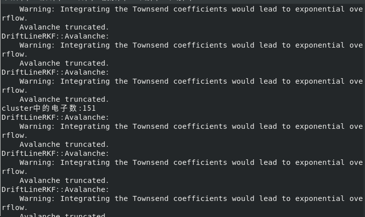
In the previous program I made modifications to use DriftRKF to simulate the drift of electrons and ions, and the simulation results were very good at first; but later when I changed the voltage on the wire(Va), there were many warnings output on the terminal, and the calculated signal It is also abnormal (the signal is much larger); is this caused by the abnormal calculation of the electric field using ComponentAnalyticField()?
Hi,
the calculation of the electric field is still ok. The warning occurs when DriftLineRKF calculates the gain along the drift line, using the table of Townsend coefficients as function of electric field that you loaded when importing the gas file. If the integral is too high such that it would lead to exponential overflow, the avalanche size is truncated.
It means that either the voltages are not set to realistic values, or that there is an issue with the gas table you are using (if it doesn’t include high enough electric fields, the extrapolation of the Townsend coefficient could go wrong).
Hi!
Thanks a lot, everything worked fine after I re-imported the gas file