Guard ring around a circular electrode

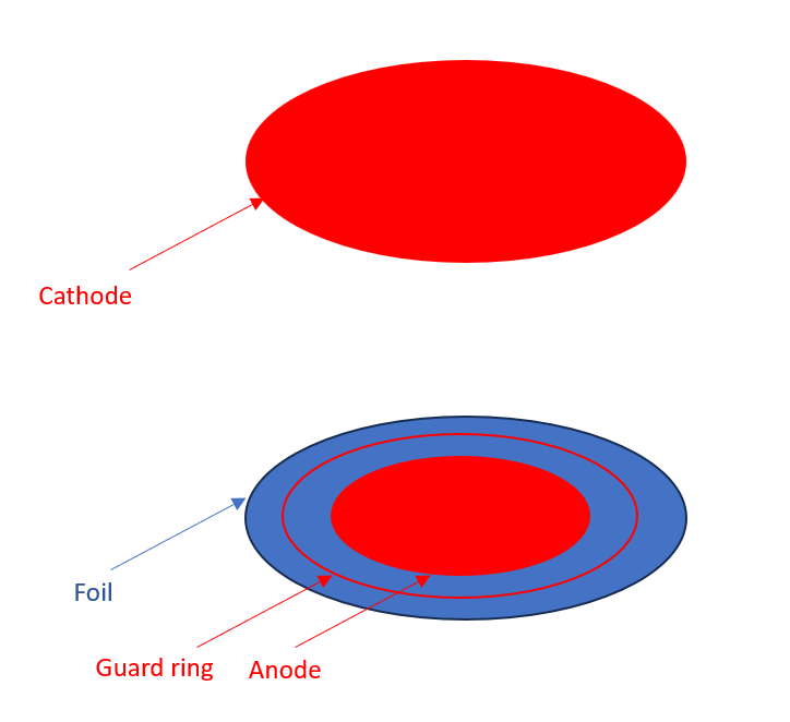
Hi all, I’m trying to define a guard ring around a circular electrode using Garfield and nebem, and obviously i don’t understand something. I thought this was possible by defining a series of flat cylinders representing the different materials, something like that:

MediumConductor Cu;
MediumPlastic Kp;
Kp.SetDielectricConstant(4.0);

GeometrySimple geo;

SolidTube Insul1(0,0, 0,ChamberRadius,ElectrodeThickness/2);
Insul1.SetSectors(4);
SolidTube Guard(0,0, 0,ChamberRadius-0.1,ElectrodeThickness/2);
Guard.SetSectors(4);
SolidTube Insul2(0,0, 0,ChamberRadius-0.2,ElectrodeThickness/2);
Insul2.SetBottomLid(false);
Insul2.SetTopLid(false);
Insul2.SetSectors(4);
SolidTube Anode(0,0, 0,ChamberRadius-0.3,ElectrodeThickness/2);
Anode.SetSectors(4);
Anode.SetLabel(“s”); // set it as the electrode

// set potentials
Insul1.SetBoundaryDielectric();
Guard.SetBoundaryPotential(AnodeVoltage);
Insul2.SetBoundaryPotential(AnodeVoltage); // or SetBoundaryDielectric()? but does not make sense in contact of conductors…?
Anode.SetBoundaryPotential(AnodeVoltage);

// add components to the geometry
geo.AddSolid(&Insul1, &Kp);
geo.AddSolid(&Guard, &Cu);
geo.AddSolid(&Insul2, &Kp);
geo.AddSolid(&Anode, &Cu);

But it does not work at all: first nebem fails to initialize if all the elements have the same thicknesses, so i have to increase the inner ones. Also the field lines don’t “avoid” the kapton as I would expect. I guess I don’t understand how to set the boundary conditions between the dielectric and the conductor materials.

Thanks in advance for your help :slight_smile:

Hi @Sebastien,

thank you for reaching out on the forum. Maybe @hschindl could take a look?

Cheers,
Marta

ok thanks :slight_smile: meanwhile i noticed that the nebem initialization does not fail using the same thicknesses if i increase the nmax parameter from SetMinMaxNumberOfElements() (in my case, going from 15 to 16 works, no idea why!)

Hi Sebastien,
I’m not 100% sure I understand the geometry. Do you have a simple sketch (hand-drawn would be fine)?

I mean something like that :slight_smile: (i did not represent the cylinder wall) Of course in the code I sent, the anode and guard ring are within the foil which is not realistic, but my main issue is how to simulate in Garfield/nebem a metallic ring in contact with an insulator :slight_smile: I hope it is more clear!

Ah, I see :wink: The ComponentNeBem3d class looks for touching surfaces (and identify/eliminate overlaps) but does not check for intersections of solids. What should work is putting the anode disk and guard ring on top of the foil disk. Then the surface areas where the guard ring or anode touch the foil should be assigned fixed-voltage boundary conditions (i. e. the potential of the anode and guard ring, respectively). And for the remaining surfaces of the foil, dielectric-dielectric boundary conditions will be used. Can you give it a try? If it doesn’t work let me know…

Thanks for your answer :slight_smile: This is what i wanted to do initially, but i could not find a way to make a ring (i.e with a given thickness) using the available geometry templates. This is why I then tried with several cylinders in each other. Is there a possibility to make such a ring?
Thanks again!

So, doing what you propose (means, so far, under the assumption that the ring is infinitely thin) the situation is indeed much better in terms of potential and field maps. In particular, the weighting field map shows no oscillation anymore on top of the anode.
So my only issue left is the thickness of the guard ring. I guess if there is no way to do it with the current version of the code, I can live with a thin one :slight_smile:

This topic was automatically closed 14 days after the last reply. New replies are no longer allowed.