Dear Experts, I am simulating an MPGD with neBEM. The geometry is a simple parallel plate with an insulator layer on top of the lower conductor plate/backplane and alternating field/sense strips on top of the insulator (glass in this case).
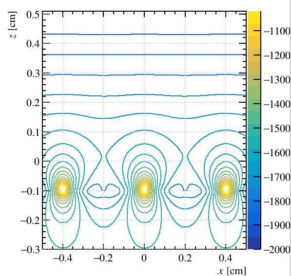
If the glass is very thin (eg 50 um) i have found that the potential (and field) lines produced by the strips cross the conductor backplane. I would have expected the conductor to shield any potential lines, but i does not seem to be the case.
I have tried replicating the effect with ComponentAnalyticField by placing a charge (10^15*electron charge) close to a conductor plate but could not reproduce the effect (i.e. the charge was completely shielded).
I have also carried out a simple COMSOL crosscheck with a conductor plate and a wire and again the field from the wire was completely shielded.
I have even tried to set a finite thickness to the conductor plate in neBEM, but again i got potential lines produced by the strips propagating into the conductor and then beneath, just as if was a dielectric.
Is this expected?
I attach a minimal working example and a snapshot of the potential lines (the lower plate is positioned near Z=-0.1).
using namespace Garfield;

int main(int argc, char* argv[]) {

   TApplication app("app", &argc, argv);

  MediumMagboltz gas;//("Ar", 87.5, "CO2", 12.5);
  gas.LoadGasFile("/afs/cern.ch/work/g/gzunica/garfield/Examples/GasFile/ar_93_co2_7.gas");
  gas.LoadIonMobility("/afs/cern.ch/work/g/gzunica/garfield/Data/IonMobility_Ar+_Ar.txt");
  gas.SetPressure(760.);
  gas.SetTemperature(293.15);

  MediumConductor Cu;
  MediumPlastic glass;
  glass.SetDielectricConstant(10.0);

  // Geometry.
  GeometrySimple geo;

  const double cat_v=-2000.;
  const double sense_v=+10.;
  const double field_v=-1700.;
  const double backplane_v=-1700.;

  const double half_tck = 0.00015;
  const double tck_glass=0.00525; //glass half tck
  const double glass_z=-0.1;
  const double bkpln_z=glass_z-tck_glass;
  const double cat_z=0.5;
  const double strip_z=glass_z+tck_glass+half_tck;

  SolidBox box1(0, 0, cat_z, 0.4,0.5, 0.0);
  box1.SetBoundaryPotential(cat_v);

  SolidBox box2(0, 0, glass_z, 0.4,0.5, tck_glass);
  box2.SetBoundaryDielectric();

  SolidBox box3(0, 0, bkpln_z, 0.4,0.5, 0.0);
  box3.SetBoundaryPotential(backplane_v);

  geo.AddSolid(&box1, &Cu);
  geo.AddSolid(&box2, &glass);
  geo.AddSolid(&box3, &Cu);

  const double radiusS = 0.0015;
  const double radiusF = 0.005;
  const double halflength = 0.5;

  double xposF = -0.2;
  double xposS = 0.0;
  double passo = 0.4;

  xposS=-0.4;
  std::vector<SolidBox*> stripsS(3, nullptr);
  for (int i = 0; i < 3; ++i) {

    stripsS[i] = new SolidBox(xposS, 0.0, strip_z, radiusS, halflength,half_tck );  // alternate strips
    if(i==0)  stripsS[i] = new SolidBox(xposS+radiusS/2, 0.0, strip_z, radiusS/2, halflength,half_tck );
    if(i==2)  stripsS[i] = new SolidBox(xposS-radiusS/2, 0.0, strip_z, radiusS/2, halflength,half_tck );
    stripsS[i]->SetBoundaryPotential(sense_v);
    stripsS[i]->SetLabel("readout");
    geo.AddSolid(stripsS[i], &Cu);
    xposS += passo ;
  }

  std::vector<SolidBox*> stripsF(2, nullptr);
  for (int i = 0; i < 2; ++i) {
    stripsF[i] = new SolidBox(xposF, 0.0, strip_z, radiusF, halflength,half_tck);
    stripsF[i]->SetBoundaryPotential(field_v);
    geo.AddSolid(stripsF[i], &Cu);
    xposF += passo ;
  }

  geo.PrintSolids();
  geo.SetMedium(&gas);

  ComponentNeBem3d nebem;
  nebem.SetGeometry(&geo);
  nebem.SetTargetElementSize(0.2);
  nebem.SetMinMaxNumberOfElements(1, 100);
  nebem.SetPeriodicityX(0.8);
  nebem.SetPeriodicityY(1.);
  nebem.SetPeriodicCopies(3,5,0);
  nebem.Initialise();

  TCanvas c("c", "", 600, 600);
  ViewField fieldView(&nebem);
  fieldView.SetPlaneXZ();
  fieldView.SetCanvas(&c);
  fieldView.SetArea(-0.5, -0.1, -0.3, 0.5, 0.1, 0.51);
  fieldView.EnableAutoRange();
  fieldView.PlotContour("v");

  gSystem->ProcessEvents();

  app.Run(true);

}