Dear Experts,
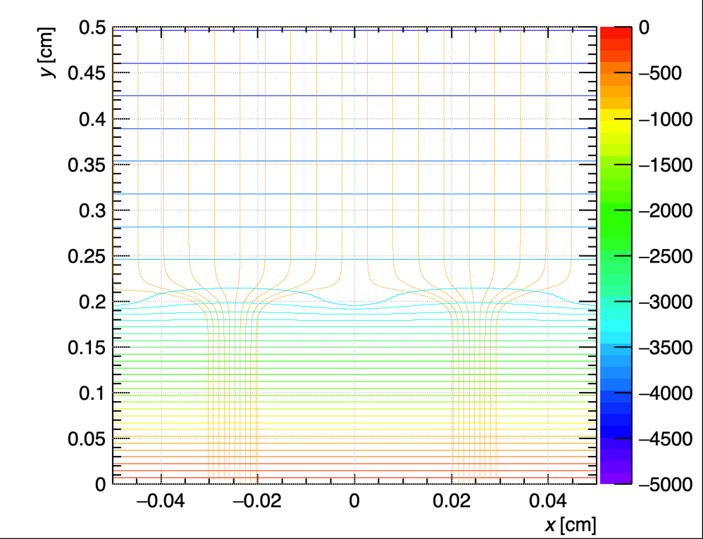
This is a R&D project im working on. Its essentially a MicroMegas detector. However, I have replaced the Micromesh with a wire layer where all the wires run parallel to each other. I have placed the Anode at 0 position with 0 voltage, Wire layer 2mm above the anode at -3500V, and cathode 5mm above the anode at -4500V. I built it with the help of GEM and fieldlines examples. The Code runs and I was able to generate plots of field lines and drift lines. However when executed, it return following error.
DriftLineRKF::FieldLine: Step size has become smaller than int. accuracy. Stop.
Please let me me know whats causing this and if its gonna affect my results. I also want to understand why I cannot cannot see any field lines going from Anode to wires. I can only see field lines going from Anode to Cathode.
Let me share my code here.
#include <cstdlib>
#include <iostream>
#include <memory>
#include <chrono>  // For timing
#include <omp.h>   // For OpenMP parallelization

#include <TApplication.h>
#include <TCanvas.h>
#include <TH1F.h>

#include "Garfield/ComponentAnalyticField.hh"
#include "Garfield/ViewField.hh"
#include "Garfield/ViewFEMesh.hh"
#include "Garfield/MediumMagboltz.hh"
#include "Garfield/Sensor.hh"
#include "Garfield/AvalancheMicroscopic.hh"
#include "Garfield/AvalancheMC.hh"
#include "Garfield/Random.hh"
#include "Garfield/Plotting.hh"
#include "Garfield/ViewCell.hh"


using namespace Garfield;

int main(int argc, char * argv[]) {
  TApplication app("app", &argc, argv);
  plottingEngine.SetPalette(1);

  constexpr double pitch = 0.05;
  constexpr double gauge = 0.008; // wire gauge in cm
  constexpr double meshVoltage = -3500.; // wires voltage
  constexpr double meshX = 0.; // wire x position
  constexpr double meshY = 0.2; // wire y position
  constexpr double cathodePosition = 0.5;
  constexpr double cathodeVoltage = -4500;

  // Gas mixture
  MediumMagboltz gas("Ar", 70., "co2", 30.);
  gas.SetTemperature(293.15);
  gas.SetPressure(760.);
  gas.Initialise(true);

  // Penning transfer coefficients
  constexpr double rPenning = 0.57;
  constexpr double lambdaPenning = 0.;
  gas.EnablePenningTransfer(rPenning, lambdaPenning, "ar");

  // Define the cell layout
  ComponentAnalyticField cmp;
  cmp.SetMedium(&gas);
  cmp.SetPeriodicityX(pitch);

  // Info on ion mobility
  const char* garfield_path = std::getenv("GARFIELD_INSTALL");
  if (!garfield_path) {
       std::cerr << "GARFIELD_INSTALL environment variable not set!" << std::endl;
       return 1;
  }
  const std::string path = garfield_path;
  gas.LoadIonMobility(path + "/share/Garfield/Data/IonMobility_Ar+_Ar.txt");

  // Add the sense wire
  cmp.AddWire(meshX, meshY, gauge, meshVoltage);

  // Add the planes
  cmp.AddPlaneY(0., 0.); // Anode
  cmp.AddPlaneY(cathodePosition, cathodeVoltage); // Cathode

  // Points above wire (y > 0.2)
  std::cout << "\nField intensity above wire:\n";
    double y1 = 0.35;
    const auto efield1 = cmp.ElectricField(0., y1, 0.);
    double magnitude1 = sqrt(efield1[0] * efield1[0] + efield1[1] * efield1[1]);
    std::cout << "At y = " << y1 << " cm:\n";
    std::cout << "  E = " << magnitude1/1000 << " kV/cm\n";

  // Points below wire (y < 0.2)
  std::cout << "\nField intensity below wire:\n";
    double y2 = 0.10;
    const auto efield2 = cmp.ElectricField(0.1, 0.1, 0.1);
    double magnitude2 = sqrt(efield2[0] * efield2[0] + efield2[1] * efield2[1]);
    std::cout << "At y = " << y2 << " cm:\n";
    std::cout << "  E = " << magnitude2/1000 << " kV/cm\n";

  // Plot isopotential contours
  ViewField fieldView(&cmp);
  constexpr double xmin = -1 * pitch;
  constexpr double xmax = 1 * pitch;
  fieldView.SetPlane(0, 0, 1, 0, 0, 0);
  fieldView.SetArea(xmin, 0., xmax, 0.5);
  fieldView.SetVoltageRange(-5000., 0.);
  TCanvas* cf = new TCanvas("cf", "Electric Field lines and Equipotential Contours", 1000, 800);
  cf->SetLeftMargin(0.16);
  fieldView.SetCanvas(cf);
  fieldView.SetNumberOfContours(40);
  fieldView.PlotContour();
  //fieldView.Plot("v", "CONT1");

  // Plot field lines
  std::vector<double> xf;
  std::vector<double> yf;
  std::vector<double> zf;

  fieldView.EqualFluxIntervals(xmin, 0.50, 0., xmax, 0.50, 0.,xf, yf, zf, 20);
  fieldView.PlotFieldLines(xf, yf, zf, true, false);

  // Plot the cell layout
  //ViewCell cellView(&cmp);
  //cellView.SetCanvas(fieldView.GetCanvas());
  //cellView.SetArea(xmin, 0., xmax, 0.5);
  //cellView.Plot2d();
  //cellView.

  // Create a sensor
  Sensor sensor;
  sensor.AddComponent(&cmp);
  sensor.SetArea(xmin, 0., xmin, xmax, cathodePosition, xmax);

  AvalancheMicroscopic aval(&sensor);
  AvalancheMC drift(&sensor);
  drift.SetDistanceSteps(2e-4);

  // Plot drifts
  ViewDrift driftView;
  constexpr bool plotDrift = true;
  if (plotDrift) {
    // Plot every tenth collision.
    aval.EnablePlotting(&driftView, 10);
    drift.EnablePlotting(&driftView);
  }

  // Count the total number of ions produced the back-flowing ions.
  unsigned int nTotal = 0;
  unsigned int nBF = 0;
  constexpr unsigned int nEvents = 20;
  for (unsigned int i = 0; i < nEvents; ++i) {
    std::cout << i << "/" << nEvents << "\n";
    // Randomize the initial position.
    const double x0 = (xmin + (xmax-xmin) * RndmUniform());
    const double z0 = (xmin + (xmax-xmin) * RndmUniform());
    const double y0 = cathodePosition;
    const double t0 = 0.;
    const double e0 = 0.1;
    aval.AvalancheElectron(x0, y0, z0, t0, e0, 0., 0., 0.);
    int ne = 0, ni = 0;
    aval.GetAvalancheSize(ne, ni);
    for (const auto& electron : aval.GetElectrons()) {
      const auto& p0 = electron.path[0];
      drift.DriftIon(p0.x, p0.y, p0.z, p0.t);
      ++nTotal;
      const auto& endpoint = drift.GetIons().front().path.back();
    if (endpoint.z > 0.005) ++nBF;
    }
  }
  std::cout << "Fraction of back-flowing ions: "
            << double(nBF) / double(nTotal) << "\n";
  std::cout << "Average Electron Gain: "
            << double(nTotal) / double(nEvents) << "\n";
    TCanvas* cd = new TCanvas("cd", "Drift View", 1000, 800);
    driftView.SetPlane(0, 0, 1, 0, 0, 0);
    driftView.SetArea(xmin, 0., xmax, 0.5);
    driftView.SetCanvas(cd);
    driftView.Plot(true);


  app.Run(true);
}
Than you very much for your assistance!
Best Regards,
Vidura