The questions about the induced current

Hi,
I have simplified the model and used the new lis files and weight file to run, the result shows killed. I used the old model, it is still the same noticing killed.
Besides, I found that I have to use the TrackHeed class ,otherwise the code below can’t be used ,and that’s the code for calculating the drift line


  const unsigned int nTracks = 1;
  size_t nClusters = 0;
  for (unsigned int j = 0; j < nTracks; ++j) {
    sensor.ClearSignal();
    // Starting point of the track.
    double xt = -0.1, yt = 0.204, zt = -0.07, tt = 0.;
    // Initial direction of the track.
    double dxt = 0., dyt = -1., dzt = 0.; 
    **track.NewTrack(xt, yt, zt, tt, dxt, dyt, dzt);**
    // Loop over the clusters on the track.
    double xc = 0., yc = 0., zc = 0., tc = 0., ec = 0., extra = 0.;
    int nc = 0;
    while (**track.GetCluster(xc, yc, zc, tc, nc, ec, extra**)) {
      ++nClusters;
      // Loop over the electrons in the cluster.
      for (int k = 0; k < nc; k++) {
        double xe = 0., ye = 0., ze = 0., te = 0., ee = 0.;
        double dxe = 0., dye = 0., dze = 0.;
        **track.GetElectron(k, xe, ye, ze, te, ee, dxe, dye, dze);**
        drift.DriftElectron(xe, ye, ze, te);
      }
    }
  }

If I delete the TrackHeed class
the code
while (track.GetCluster(xc, yc, zc, tc, nc, ec, extra)) {
++nClusters;
and the code
track.NewTrack(xt, yt, zt, tt, dxt, dyt, dzt);
will notice error

Yes of course. If you delete the lines of code that create and configure a TrackHeed object, you cannot use this object in your program. I don’t understand what’s the question here.

You can but you don’t have to use TrackHeed if you want to simulate drift lines from a charged-particle track. If you want to use TRIM, you can do something like in this example to which I pointed you earlier and which you used in a previous version of your program.

Hi,
Thanks a lot for your reply
I know it now, the drift line come from my TRIM files right? Now I have better understanding about the Garfield++ and their relationship.

#include <iostream>
#include <TApplication.h>
#include <TH1F.h>
#include <TCanvas.h>

#include "Garfield/MediumSilicon.hh"
#include "Garfield/ComponentConstant.hh"
#include "Garfield/Sensor.hh"
#include "Garfield/TrackTrim.hh"
#include "Garfield/DriftLineRKF.hh"
#include "Garfield/ViewDrift.hh"
#include "Garfield/ViewSignal.hh"
#include "Garfield/ComponentAnsys123.hh"
#include "Garfield/MediumMagboltz.hh"
#include "Garfield/ViewField.hh"
#include "Garfield/TrackHeed.hh"

using namespace Garfield;

int main(int argc, char *argv[]) {

  // Application
  TApplication app("app", &argc, argv);
 
  ComponentAnsys123 fm;
  fm.Initialise("ELIST.lis", "NLIST.lis", "MPLIST.lis", "PRNSOL.lis", "mm");
  fm.SetWeightingField("weight.lis", "readout");
  double x0, y0, z0, x1, y1, z1;
  fm.GetBoundingBox(x0, y0, z0, x1, y1, z1);

  ViewField fieldView;
  constexpr bool plotField = true;
  if (plotField) {
    fieldView.SetComponent(&fm);
    // Set the normal vector of the viewing plane.
    fieldView.SetPlane(0, 0, -1, 0, 0, 0.5 * (z0 + z1));
    fieldView.PlotContour();
    //fieldView.PlotFieldLines(xf, yf, zf, true, true, kOrange-3); 
  }


  // Define the medium.
  MediumMagboltz gas;
  gas.LoadGasFile("He-740Torr.gas");
  fm.SetMedium(0, &gas);

  Sensor sensor;
  sensor.AddComponent(&fm);
  sensor.AddElectrode(&fm, "readout");
  sensor.SetTimeWindow(0., 1000., 100);
  sensor.GetSignal("readout",1000);

  // Read the TRIM output file. 
  TrackTrim tr;
  const std::string filename = "EXYZ-He.txt";
  // Import the first 100 ions.
  if (!tr.ReadFile(filename, 500)) {
    std::cerr << "Reading TRIM EXYZ file failed.\n";
    return 1;
  }
  tr.SetWorkFunction(26);
  tr.SetFanoFactor(0.179);
  // Connect the track to a sensor.
  tr.SetSensor(&sensor);

  DriftLineRKF drift;
  drift.SetSensor(&sensor);
  drift.SetMaximumStepSize(10.e-4);

  // Plot the track and the drift lines.
  ViewDrift driftView;
  tr.EnablePlotting(&driftView);
  drift.EnablePlotting(&driftView);
  
  // Simulate an ion track.
  tr.NewTrack(0., 0., 0., 0., 0., 1., 0.);
  // Loop over the clusters.
  double xc, yc, zc, tc, ec, ekin;
  int ne = 0;
  while (tr.GetCluster(xc, yc, zc, tc, ne, ec, ekin)) {
    // Simulate electron and ion drift lines starting 
    // from the cluster position. 
    // Scale the induced current by the number of electron/ion pairs 
    // in the cluster.
    drift.SetElectronSignalScalingFactor(ne);
    drift.DriftElectron(xc, yc, zc, tc);
    drift.SetHoleSignalScalingFactor(ne);
    drift.DriftHole(xc, yc, zc, tc);
  }
  driftView.SetArea(-2.e-4, 0., 2.e-4, 100.e-4);
  driftView.Plot(true);


  ViewSignal signalView;
  signalView.SetSensor(&sensor);
  signalView.PlotSignal("readout", true, true, true);

  app.Run();
  //return 0;
}

That looks better, except that (as I told you before) you cannot use DriftHole in a gas detector.

Not really. The simulation involves two steps:

  • TrackHeed or TrackTrim simulate how many electron/ion pairs are generated by a charged particle crossing the sensor and at which locations.
  • To simulate the drift of the electrons and ions in the electric field you then use DriftLineRKF.

Hi,
Thanks a lot for your reply
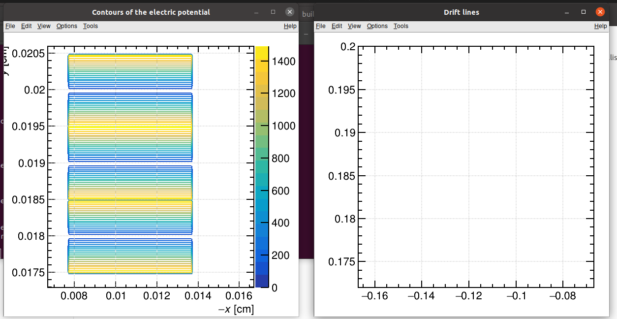
Yep, I know that the DriftHole should be deleted, because it is used for the silicon. I have modified the code, but the results still notice killed, so I just simulate the drift line first and then to the induced current signal. The drift line result don’t show the killed but the empty plot like below


And that’s my code:

#include <iostream>
#include <TApplication.h>
#include <TH1F.h>
#include <TCanvas.h>

#include "Garfield/MediumSilicon.hh"
#include "Garfield/ComponentConstant.hh"
#include "Garfield/Sensor.hh"
#include "Garfield/TrackTrim.hh"
#include "Garfield/DriftLineRKF.hh"
#include "Garfield/ViewDrift.hh"
#include "Garfield/ViewSignal.hh"
#include "Garfield/ComponentAnsys123.hh"
#include "Garfield/MediumMagboltz.hh"
#include "Garfield/ViewField.hh"
#include "Garfield/TrackHeed.hh"

using namespace Garfield;

int main(int argc, char *argv[]) {

  // Application
  TApplication app("app", &argc, argv);
 
  ComponentAnsys123 fm;
  fm.Initialise("ELIST.lis", "NLIST.lis", "MPLIST.lis", "PRNSOL.lis", "mm");
  fm.PrintRange();
  fm.PrintMaterials();
 // fm.SetWeightingField("weight.lis", "readout");
  double x0, y0, z0, x1, y1, z1;
  fm.GetBoundingBox(x0, y0, z0, x1, y1, z1);

  ViewField fieldView;
  constexpr bool plotField = true;
  if (plotField) {
    fieldView.SetComponent(&fm);
    // Set the normal vector of the viewing plane.
    fieldView.SetPlane(0, 0, -1, 0, 0, 0.5 * (z0 + z1));
    fieldView.PlotContour();
    //fieldView.PlotFieldLines(xf, yf, zf, true, true, kOrange-3); 
  }


  // Define the medium.
  MediumMagboltz gas;
  gas.LoadGasFile("He-740Torr.gas");
  fm.SetMedium(0, &gas);

  Sensor sensor;
  sensor.AddComponent(&fm);
  sensor.AddElectrode(&fm, "readout");
  sensor.SetTimeWindow(0., 1000., 100);
  sensor.GetSignal("readout",1000);

  // Read the TRIM output file. 
  TrackTrim tr;
  const std::string filename = "EXYZ-He.txt";
  // Import the first 100 ions.
  if (!tr.ReadFile(filename, 500)) {
    std::cerr << "Reading TRIM EXYZ file failed.\n";
    return 1;
  }
  tr.SetWorkFunction(42);
  tr.SetFanoFactor(0.17);
  // Connect the track to a sensor.
  tr.SetSensor(&sensor);

  DriftLineRKF drift;
  drift.SetSensor(&sensor);
  //drift.SetMaximumStepSize(10.e-4);

  // Plot the track and the drift lines.
  ViewDrift driftView;
  tr.EnablePlotting(&driftView);
  drift.EnablePlotting(&driftView);
  
  // Simulate an ion track.
  tr.NewTrack(-0.1, 0.204, -0.07, 0., 0., -1., 0.);
  // Loop over the clusters.
  double xc, yc, zc, tc, ec, ekin;
  int ne = 0;
  while (tr.GetCluster(xc, yc, zc, tc, ne, ec, ekin)) {
    // Simulate electron and ion drift lines starting 
    // from the cluster position. 
    // Scale the induced current by the number of electron/ion pairs 
    // in the cluster.
    drift.SetElectronSignalScalingFactor(ne);
    drift.DriftElectron(xc, yc, zc, tc);
  }
  driftView.SetArea(-1.67e-1, 0.172, -0.67e-1, 0.2);
  driftView.Plot(true);


  //ViewSignal signalView;
  //signalView.SetSensor(&sensor);
  //signalView.PlotSignal("readout", true, true, true);

  app.Run();
  return 0;
}

Looking at the screenshot of the contour plot, your field map extends from y = 0.0175 cm to y = 0.0205 cm but the track starts at y = 0.204 cm (way outside your field map).

You really need to figure out the dimensions of your detector.

Hi,Thanks a lot for your reply
the thickness of my detector is 30mm, but I really don’t know the reason for why the field map would show only 0.003cm.

Hi,
I know what the reason for it
when I set the code “fm.Initialise(“ELIST.lis”, “NLIST.lis”, “MPLIST.lis”, “PRNSOL.lis”, “mm”);”
the plot like this in the below


However when I set the code “fm.Initialise(“ELIST.lis”, “NLIST.lis”, “MPLIST.lis”, “PRNSOL.lis”, “cm”);”
the result is like this in the below

Hi,
I have get the drift line now, it is like this in the below, is that right? and what’s the red dotted line?


Besides ,would you please tell me how to the thickness of the detector? it is now only 0.3mm,but the real is 300mm, what’s the reason for that?

Hi,
That’s the induced current plot , it is still just a line…

What red dotted line?

The size of the detector in the simulation is entirely defined by our ANSYS field map. What length unit did you use when describing your geometry in ANSYS? If it’s cm, then the last argument of the ComponentAnsys123::Initialise function has to be "cm", if it’s m, then the argument has to be "m", etc.

Yes. As I said in one of my replies yesterday, there might be an issue with the weighting field map.


The drift line has two colors, why they are different

The weighting potential in the ansys is all right, in the Garfield++, should I use the code“ fm. Initialise(“weight.lis”,“m”);”?

The orange line corresponds to the electron drift line. The green line shows the track (TRIM clusters).

1 Like

No. You should first load the mesh and “real” potentials using fm.Initialise(...); and then load the map of weighting potentials using fm.SetWeightingField(...);
That part was fine in your program.

So there is only one cluster?

OK,the weighting potential is the same like before
https://root-forum.cern.ch/uploads/default/original/3X/1/6/168c45505862bfe70485a06f6394efa7c98ad24a.png
Is there anything wrong in the setting of the electric load in the ansys? I have set two areas to 1V as electrode, and other areas all to 0V, there has only gas areas in my model, and the gaps between the gas areas are empty.

the results is now like this:

Sensor::SetArea:
    -16.7044 < x [cm] < -6.70436
    17.2927 < y [cm] < 20.5927
    -11.5321 < z [cm] < -3.53211
DriftLineRKF::Avalanche:
    Cannot retrieve alpha at drift line point 15, segment 1.
DriftLineRKF::Avalanche:
    Cannot retrieve alpha at drift line point 24, segment 1.

what’s the meaning about"Cannot retrieve alpha at drift line point 24, segment 1."
There is no avalanche in my detector at all

Hi,
I have sent all the files needed to your email.Would you please help me to reproduce the program to see if it can work? there are a lot of weird problem in my running, solving one another coming, so please help me to see what it is going on. And Thanks a lot!

ComponentAnsys123::Initialise:
    Read properties of 2 materials from file MPLIST.lis.
ComponentAnsys123::Initialise:
    Read 2159067 elements from file ELIST.lis,
    highest node number: 3124105,
    background elements skipped: 0
ComponentAnsys123::Initialise:
    Read 3124105 nodes from file NLIST.lis.
ComponentAnsys123::Initialise:
    Read 3124105 potentials from file PRNSOL.lis.
ComponentAnsys123::Prepare:
    Caching the bounding boxes of all elements... done.
ComponentAnsys123::InitializeTetrahedralTree: Success.
ComponentAnsys123::PrintRange:
        Dimensions of the elementary block
                   -16.7044 < x < -6.70436        cm,
                    17.2927 < y < 20.5927         cm,
                   -11.5321 < z < -3.53211        cm,
                          0 < V < 1500            V.
        Periodicities
            x: none
            y: none
            z: none
ComponentAnsys123::PrintMaterials:
    Currently 2 materials are defined.
      Index Permittivity  Resistivity Notes
          0            1           -1 (drift medium)
          1         4.25        1e+10
ComponentAnsys123::SetWeightingField:
    Read 3124105 potentials from file weight.lis.
Killed