Hi ,the detector is made up of 13 panels stacked on top of each other, there are contact surfaces between each board. If I set up the contact surfaces ,the analysis become nolinear solution, otherwise the results is linear. so what should I do, and would you please help me, thanks again.
Sorry, I don’t follow. If you are plotting a field map where all potentials are zero, then it’s not surprising that the plot shows zero everywhere, no?
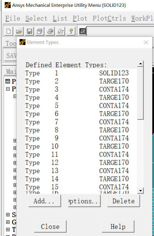
Also I don’t understand what the choice of the element type (Solid123) has to do with the boundary conditions.
Thanks a lot for your reply, Can I delete the zero voltage on the copper bar array? only keep one board zero voltage, and after import the model successfully, I set the geometric cathode and voltage.
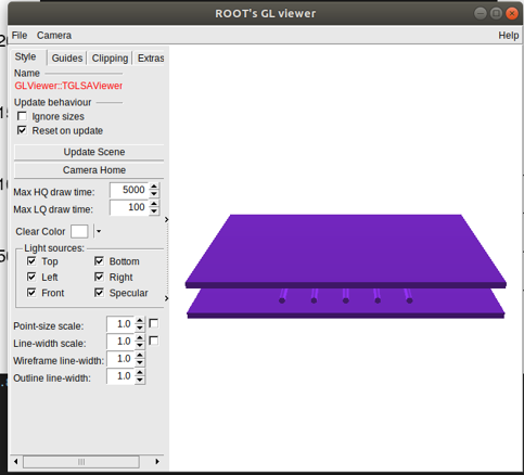
If the contour plot is empty, can I see the 3D model to make sure the ansys model works. Such as the picture in the below.
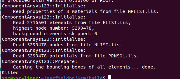
Hi, the results of the last words “killed”, I don’t know what dose it mean. I will try to modify my model and do the finite analysis again, and see whether it could be work.
I don’t know if this answers your question, but you cannot modify the boundary conditions after importing the field map, this is something you need to do in Ansys.
What you can do to reduce the size of the field map is to not export the metallic volumes since they are typically not active volumes and you know that the field inside is zero.
Ok, thanks a lot, but I can set up the gas area after importing the field map, right? I will try some other methods, and would you please tell me how to invoke the ROOT’s GL viewer, is that a way to show the 3D field mesh?
the metallic volumes are really important in the detector, if my model is right, the gas ionized in the model (such as electron)will transferred to the metallic volumes and generate induced current, and that’s the data I want to know.
It depends what you mean by that. If your field map includes a gas region then you can use Garfield++ to simulate electrons, ions, charged particle tracks, etc. in this region.
The ionisation electrons/ions produced in the gas will indeed drift to the metal electrodes and induce a current. But you don’t need the mesh elements inside the metal regions for that. Once an electron reaches the metal, the signal induced by this electron is over.
Hi,this is a really a useful information for me. but some of my metal electrodes are penetrable,some are not. when the proton comes, it has to penetrate aluminum film to ionize the gas.